15
Machine installation
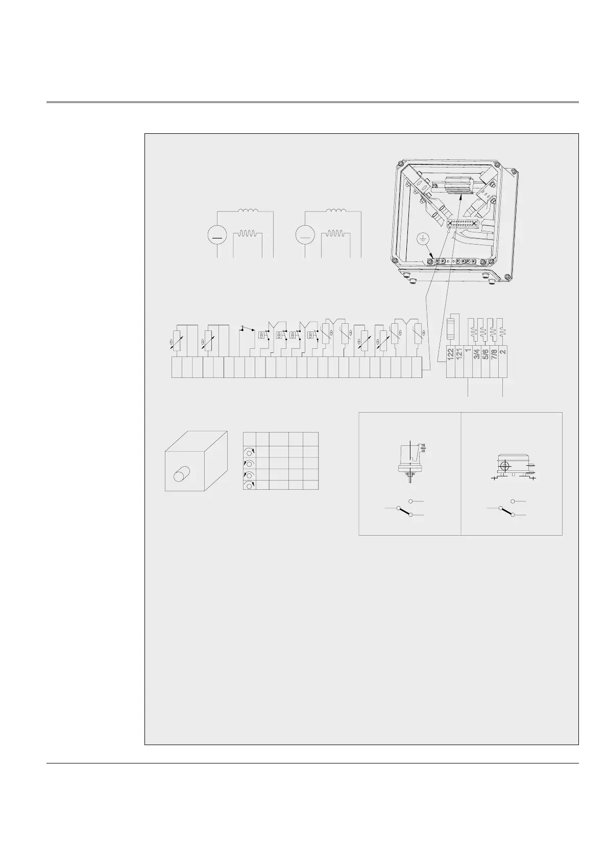
Terminal
diagram
Terminal diagram for DMI 180-280, standard design (shunt wound machine).
Fig. 9 Terminal diagram.
101, 102
Connection thermistors 3BSM 004640- on main
field coil (101) and interpole field coil series con-
nected, switch off
1)
103, 104
Connection PT 100 3BSM 004647-1 on main
field coil
1)
105, 106
Connection PT 100 3BSM 004647-1 on interpole
field coil
1)
111, 112
Connection thermistors 3BSM 004640- on main
field coil (111) and interpole field coil series con-
nected, alarm
1)
113, 114
Connection thermostats 3BSM 004641- on main
field coil (113) and interpole field coil series con-
nected, switch off
1)
115, 116
Connection thermostats 3BSM 004641- on main
field coil (115) and interpole field coil series con-
nected, alarm
1)
117, 118
Connection brush wear protection acc to order
1)
121, 122
Connection heater
1)
131, 132, 133
Connection PT 100 for bearings on D-end
1)
141, 142, 143
Connection PT 100 for bearings on D-end
1)
1)
If provided
GeneratorMotor
Pressure switch Filter monitor
Supply lead
”Pressure on”
”Pressure off”
Supply lead
”Filter dirty”
A
1
A
1
B
2
-
+
-
+
+
-
-
+
+
-
-
+
+
-
+
-
113
116
131
132
133
118
117
115
114
111
112
105
106
102
103
104
101
3/4
F1
122
121
1
F2*
5/6
7/8
2
F2
F1
A2
A1 A1
M G
A2
F2
F1
A1
A2
143
141
142
A1 A2 F1 F2*
1
3
2 2
1
3
”Filter not
dirty”
* Former designated F4. Changed to F2 according to IEC 60034-8.
 Loading...