- 95 -
000839BG
5 - Installation
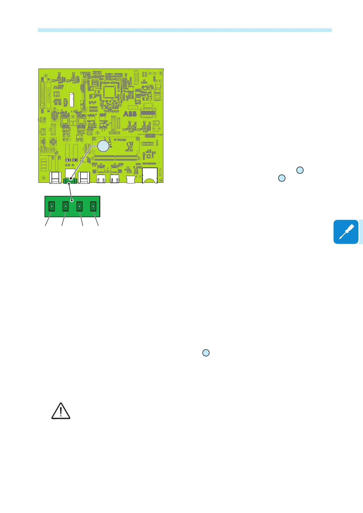
Remote control connection
The connection and disconnection of the inverter to and
from the grid can be controlled through an external control.
The function must be enabled in the relevant menu of
the Web User Interface. If the remote control function is
disabled, the switching on of the inverter is dictated by the
presence of the normal parameters which allow the inverter
to connect to the grid.
If the remote control function is operating, besides being
dictated by the presence of the normal parameters that allow
the inverter to connect to the grid, the switching on of the
inverter also depends on the state of the R1 and R2 terminals
compared to the RTN terminal present on the
37
connector
of the communication and control board
28
.
When one of the R1 or R2 signals is brought to the same
potential as the RTN signal (i.e. by making a short circuit
between the two terminals of the connector), this causes the
inverter to disconnect from the grid.
The connections of these controls are made between the
R1 and the R2 inputs compared to the common RTN signal.
Since this is a digital input, there are no requirements to
be observed as regards cable cross-section (it only needs
to comply with the sizing requirement for passing cables
through the cable glands and the terminal connector).
Demand Response Mode 0 (AS/NZS 4777.2)
Where requested by the AS/NZS 4777.2 standard, it’s possible to use the
Remote terminal block
37
for the Demand Response Mode 0 (DRM0)
functionality.
Refer to dedicated DRM0-INTERFACE product documentation to know
how to properly connect the device to the inverter.
For further information regarding the DRM0 function refer to the AS/NZS 4777 standard.
J2 X1
X2
S5S4
J7
J1
J5 J6
1
2
1
8
7
432
ZGN.V2Q15.2
R1 R2 RTNRTN
37
 Loading...


