12 Quick Installation Guide - PVS-175-TL “A.1 Version”
EN
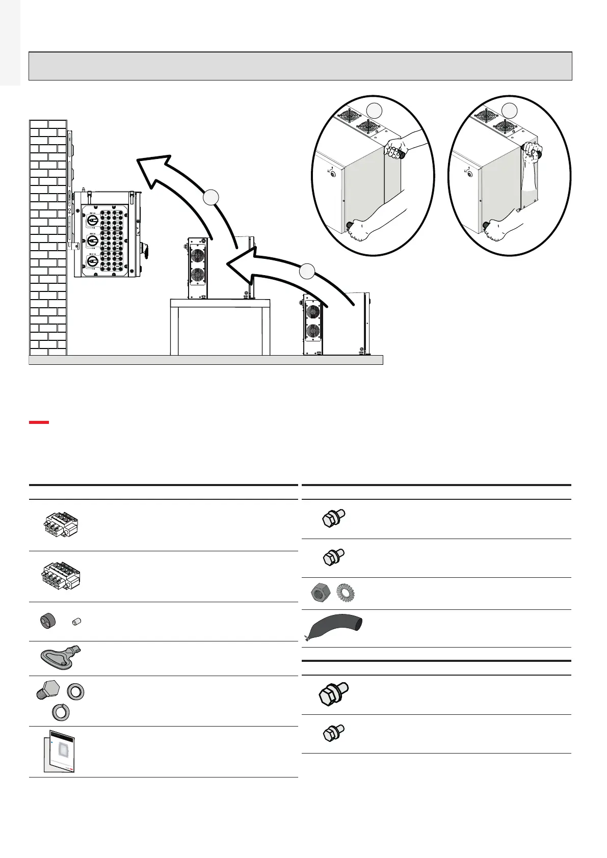
ATTENTION – A In case of manual lifting it’s suggested to use a support plan (e.g. a table) to place
the equipment during the lifiting operation, to allow the change of hands position.
BA
A
B
5. List of supplied components
Available components for wiring box Qty
Connector for connection of
the configurable relay (41) and
aux relay (41) (pre-installed on
communication board (26))
2
Connector for connecting the
Remote ON/OFF (42) signal and
RS485 (43) (pre-installed on
communication board (26))
3
Two-hole gasket (6mm Ø) for
PG21 service cable glands (13)
and cap
2+2
Key tool for front covers quarter
cam-lock (05)
1
M8 bolt and washers for external
protective earth connection
point (10)
1+1+1
In addition to what is explained in this guide, the safety and installation information provided in the installation manual must be read and followed.
The technical documentation and the interface and management software for the product are available at the website.
XXXXXXXXXXXXXXXXXXX
XXXXXXXXXXXXXXXXXXX
ABB solar inverters
Technical documentation 1
Available components for power module Qty
M6 bolts with washers for AC
interface connection point
(phases) (34)
3
M5 bolts with washers for AC
interface connection point (MID
BULK) (34)
1
M5 nut and washers for Interface
protective earth point (36)
1+2
Sheating for DC interface cables
(33)
2
Available components for brackets Qty
M8 bolts with washers for
mechanically securing the half-
brackets
2
M6 screws for mechanically
securing the wiring box to the
bracket
2
 Loading...


