4 Quick Installation Guide - PVS-175-TL “A.1 Version”
EN
1. Reference number index
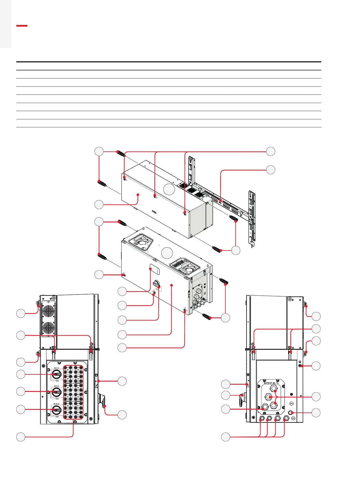
Inverter external view
01 Power module 08 Status LEDs 15 Cover support brackets
02 Wiring box 09 AC disconnect switch (-SX2, -S2 only) 16 Side latches
03 Mounting bracket 10 Protective earth point (ext.) 17 Rear pins for bracket assembly
04 Handles 11 Phases cable glands 18 DC input quick fit connectors
05 Cover quarter cam locks 12 Protective earth cable gland 19 DC disconnect switches
06 Front power module cover 13 Signal cable glands
07 Front wiring box cover 14 RS485 Service connector
PVS
03
01
02
17
17
06
09
17
17
15
18
13
05
08
09
07
05
11
19
19
19
04
05
04 05
16
04
14
10
04
16
12
15
09
 Loading...


