23
EN
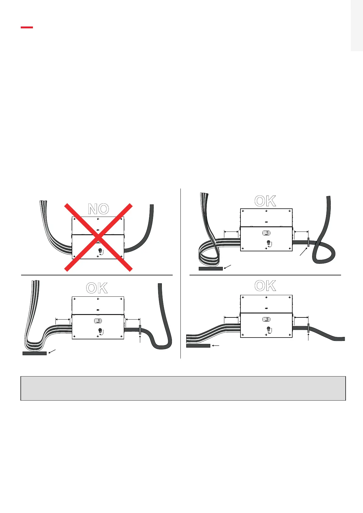
8. Routing the cable to the inverter
The cable routing have to be done in order to avoid water dripping to the AC panel cable glands (11) (12), DC
input quick fit connectors (18) or to signal cable glands (13).
Expecially when coming from the top, the cables must be routed in order to create a loop: in this way the
water that flows on the cables will be drained.
The AC and DC conductors must be anchored or supported in order to prevent loading and mechanical stress
on the cable glands and quick fit connectors causing potential damage on the AC and the DC plates.
The pictures below are showing some example of incorrect and proper cable routing.
PVS-175
PVS-175
PVS-175
PVS-175
OK
OK
OK
NO
20-30 cm
Min. of
straight
cable
20-30 cm
Min. of
straight
cable
20-30 cm
Min. of
straight
cable
20-30 cm
Min. of
straight
cable
20-30 cm
Min. of
straight
cable
20-30 cm
Min. of
straight
cable
Insert strain
relief here
Support the cables
(e.g. with a cable tray)
Support the cables
(e.g. with a cable tray)
Support the cables
(e.g. with a cable tray)
Insert strain
relief here
Insert strain
relief here
ATTENTION – A In case of the AC cable glands (11) was accidentally removed during the cable routing
phase, it will needed to assure the correct tightness of the lock nut of the cable gland to the inverter
chassis with a tightening torque of 8.0 Nm (for each cable gland).
 Loading...


