1MRS750527-MUM
)HHGHU7HUPLQDO
Technical Reference Manual, General
5()B
29
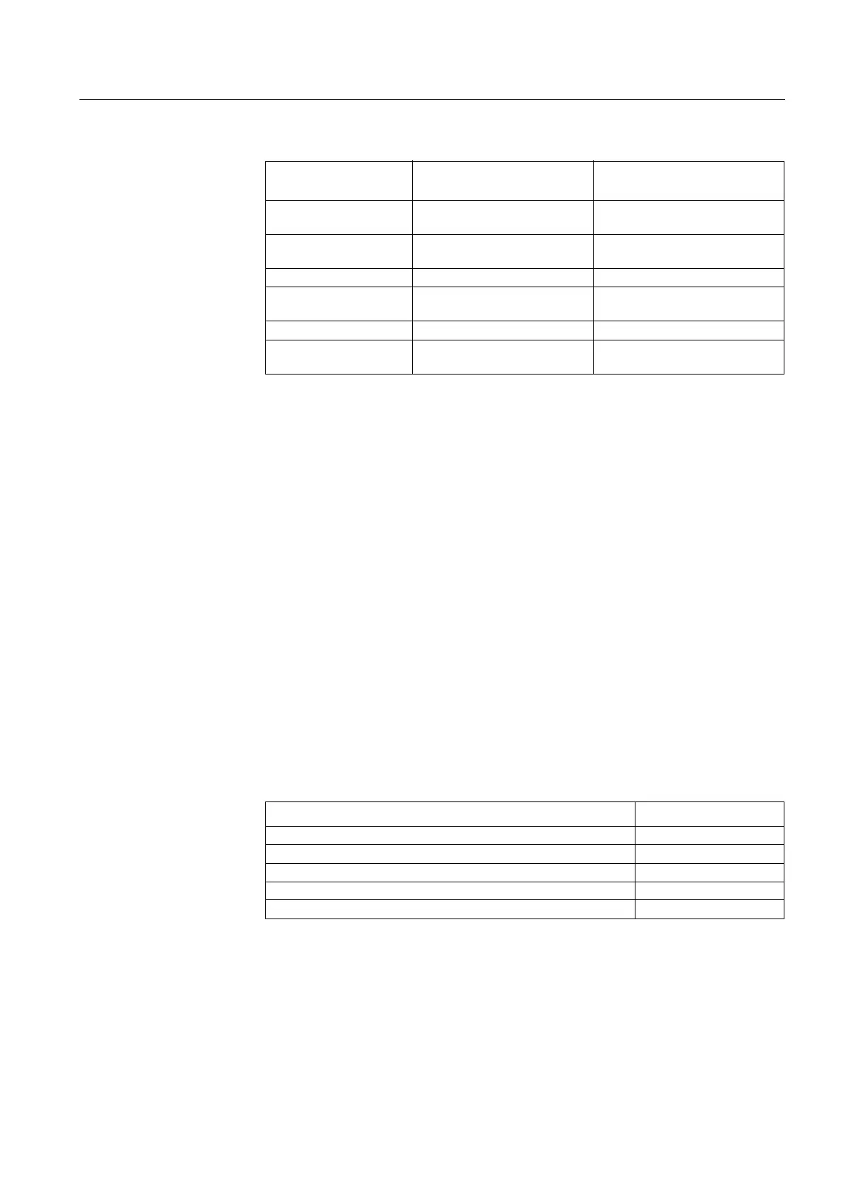
The auxiliary voltages of power supply modules and the corresponding rated input
voltages of digital inputs are:
When REF 54_ is delivered with a fixed display module, the input voltage range of
the power supply module is marked on the front panel of the feeder terminal. When
the feeder terminal is provided with an external display module, the input voltage of
the display module is marked on the front panel of the module and the input voltage
of the main unit is marked on the side of the unit.
The external display module is only available together with a main unit equipped
with the PS_/240 power supply module.
The power supply version is specified by the first letter in the order number of REF
54_ (refer to section “Ordering Information” on page 88). The voltage range of the
digital inputs is tied to the selected power supply. If a power supply version with the
higher rated input voltage is selected, the feeder terminals will be delivered with
digital inputs that also have the higher rated input voltage.
For further technical data of the power supply, refer to Table 4.2.1-2 on page 75.
/RZDX[LOLDU\YROWDJHLQGLFDWLRQ
The REF 54_ feeder terminal is provided with a low auxiliary voltage indication
feature. The power supply module issues an internal alarm signal when a drop in the
power supply voltage is detected (ACFail, active low). The alarm signal is activated
if the power supply voltage falls about 10% below the lowest rated dc input voltage
of the power supply module, see the table below:
The indication of a low auxiliary voltage (ACFail) is available in the feeder terminal
configuration environment and can be connected to any signal output of the REF
54_. The auxiliary voltage indication in the feeder terminal configuration is as
follows:
3RZHUVXSSO\PRGXOH
5DWHGLQSXWYROWDJH
RISRZHUVXSSO\
5DWHGLQSXWYROWDJH
RIGLJLWDOLQSXWV
PS1/240 V (High) 110/120/220/240 V ac
or 110/125/220 V dc
220 V dc
PS1/240 V (Medium) 110/120/220/240 V ac
or 110/125/220 V dc
110/125/220 V dc
PS1/48 V (Low) 24/48/60 V dc 24/48/60/110/125/220 V dc
PS2/240 V 110/120/220/240 V ac
or 110/125/220 V dc
-
PS2/48 24/48/60 V dc -
External display module 110/120/220/240 V ac
or 110/125/220 V dc
-
5DWHGLQSXWYROWDJH /RZLQGLFDWLRQOHYHO
PS_/240
• Rated input voltage 110/125/ 220 V dc 99 V dc
• Rated input voltage 110/120/220/ 240 V ac 88 V ac
PS_/48
• Rated input voltage 24/48/60 V dc 21.6 V dc

 Loading...


