1MRS750527-MUM
)HHGHU7HUPLQDO
Technical Reference Manual, General
5()B
83
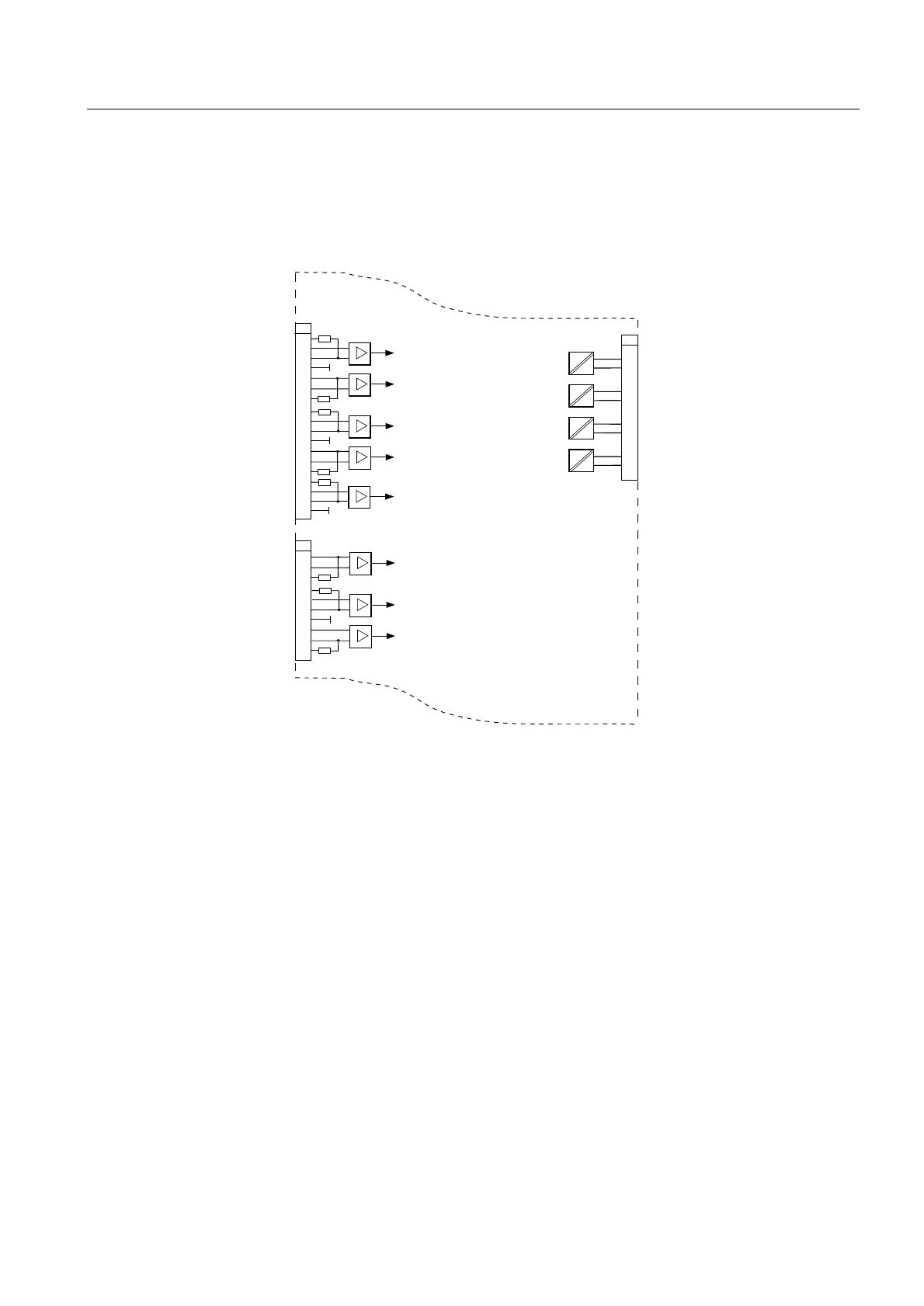
7HUPLQDOGLDJUDPRIWKH57'DQDORJXHPRGXOH
Terminal diagrams for the REF 541 and REF 543 feeder terminals provided with an
RTD/analogue module are similar to the diagrams presented in sections “Terminal
diagram of REF 541” on page 80 and “Terminal diagram of REF 543” on page 81,
except for the part illustrating the RTD/analogue module (see below), which is
added to the diagrams considering the slot numbers.
7HUPLQDOFRQQHFWLRQV
All external circuits are connected to the terminal blocks on the rear panel. Terminal
block X1.1 for the measuring transformers consists of fixed screw terminals
fastened to the energizing input module. Each terminal is dimensioned for one max.
6 mm
2
or two max. 2.5 mm
2
wires.
ABB sensors (Rogowski coil or voltage divider) are connected to the connectors
X2.1...X2.9. A special type of shielded twin BNC connector (e.g. type AMP 332225
or Amphenol 31-224) is used to improve reliability and protection against
disturbances. The current and/or voltage sensor used must have a connector that is
compatible with the feeder terminal. If the feeder terminal is ordered without sensor
inputs, the sensor connectors X2.1...X2.9 are missing. Short-circuit connectors
(1MRS120515) must be connected to unused sensor inputs.
The serial interface RS-232 on the rear panel (connector X3.2) is used for
connecting the REF 54_ to the SPA bus or the IEC_103. The SPA/IEC_103 bus is
connected to the X3.2 via a connection module RER 123 and a cable with a 9-pin D-
type subminiature female connector at both ends. The other end of the cable is
X6.2
RTD1_6_AI1
DIFF
RTD1_6_AI2
DIFF
RTD1_6_AI3
DIFF
RTD1_6_AI4
DIFF
RTD1_6_AI5
DIFF
X6.2
4
5
6
7
1
2
3
8
9
10
RTD1_6_AI6
DIFF
RTD1_6_AI7
DIFF
RTD1_6_AI8
DIFF
11
12
13
14
15
16
17
18
X6.1
5
6
7
1
2
3
4
12
13
14
8
9
10
11
15
16
17
18
+
-
+
-
+
-
+
-
SHUNT
SHUNT
SHUNT
SHUNT
SHUNT
SHUNT
SHUNT
SHUNT
-
+
-
+
-
+
-
+
RTD1_6_AO1
mA
+
-
RTD1_6_AO2
mA
+
-
RTD1_6_AO3
mA
+
-
RTD1_6_AO4
mA
+
-
RTD1diag

 Loading...


