17
1. The backlight is turned on after the relay has performed the internal power-up
tests and entered into the protection mode.
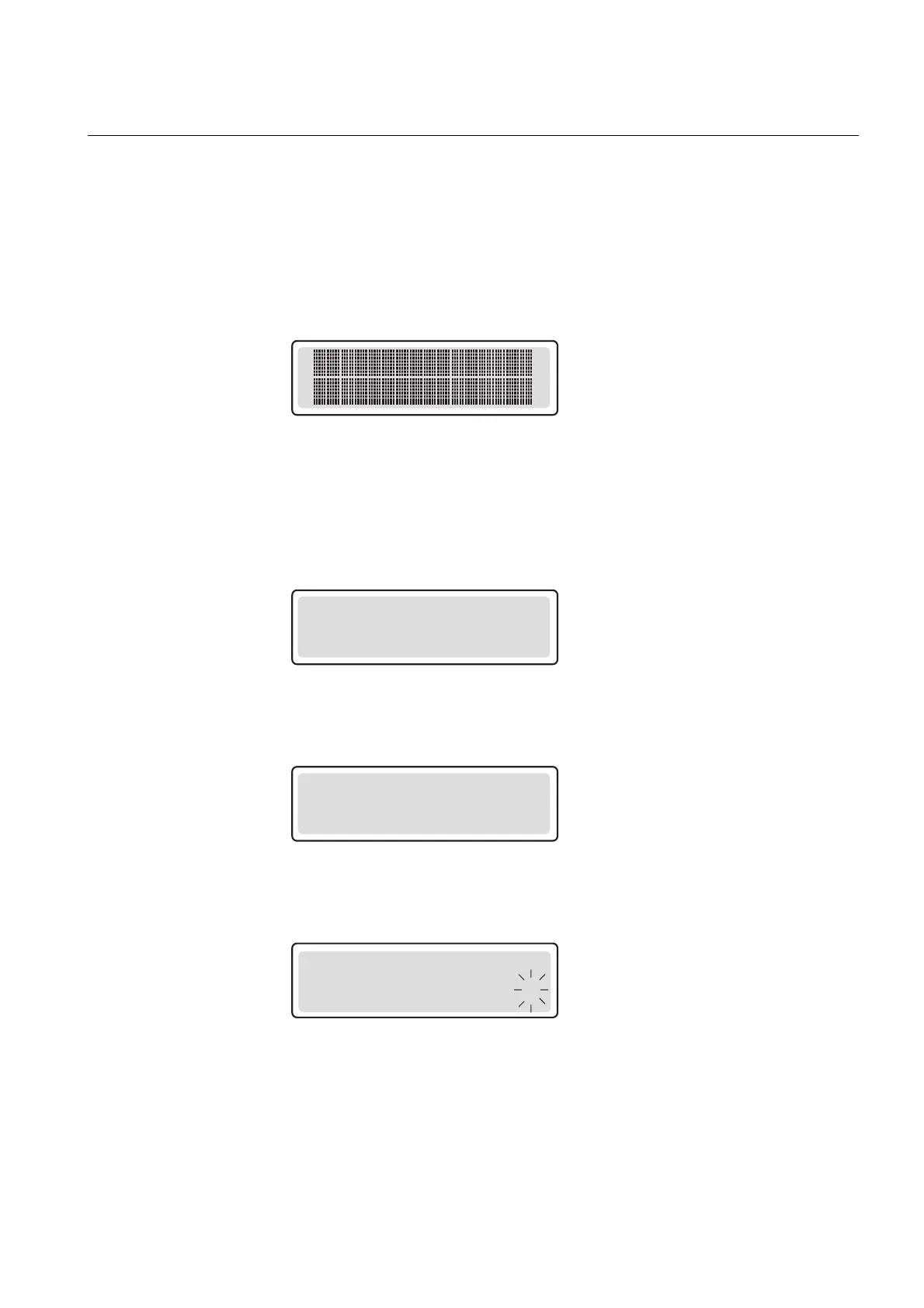
2. The display is tested by inverting it for approximately three seconds, see
Fig. 4.1.3.1.-1.
3. The display is returned to the idle mode and the backlight is turned off if no
operation target message is displayed. However, if the non-volatile function is
active, a message shown on the display before the auxiliary voltage was
disconnected reappears on the display.
A040216
Fig. 4.1.3.1.-1 Display test at power up, display inverted
4.1.3.2. Display modes
When the display is in the idle mode, the name of the feeder is displayed, which by
default is - ABB -. To change the name of the feeder, use SPA parameter M20.
- ABB -
A040217
Fig. 4.1.3.2.-1 Display in the idle mode
When the display is in the view mode, you can only view the settings.
SETTINGS
*GRP1 : 3.50
A040218
Fig. 4.1.3.2.-2 Display in the view mode
When the display is in the setting mode, you can also edit the settings.
SETTINGS
*GRP1 : 3.5 1
A040219
Fig. 4.1.3.2.-3 Display in the setting mode
4.1.3.3. Display backlight
Normally the backlight of the display is off.
Feeder Protection Relay
Operator's Manual - ANSI Version
REF 610REF 610
1MRS755539
 Loading...


