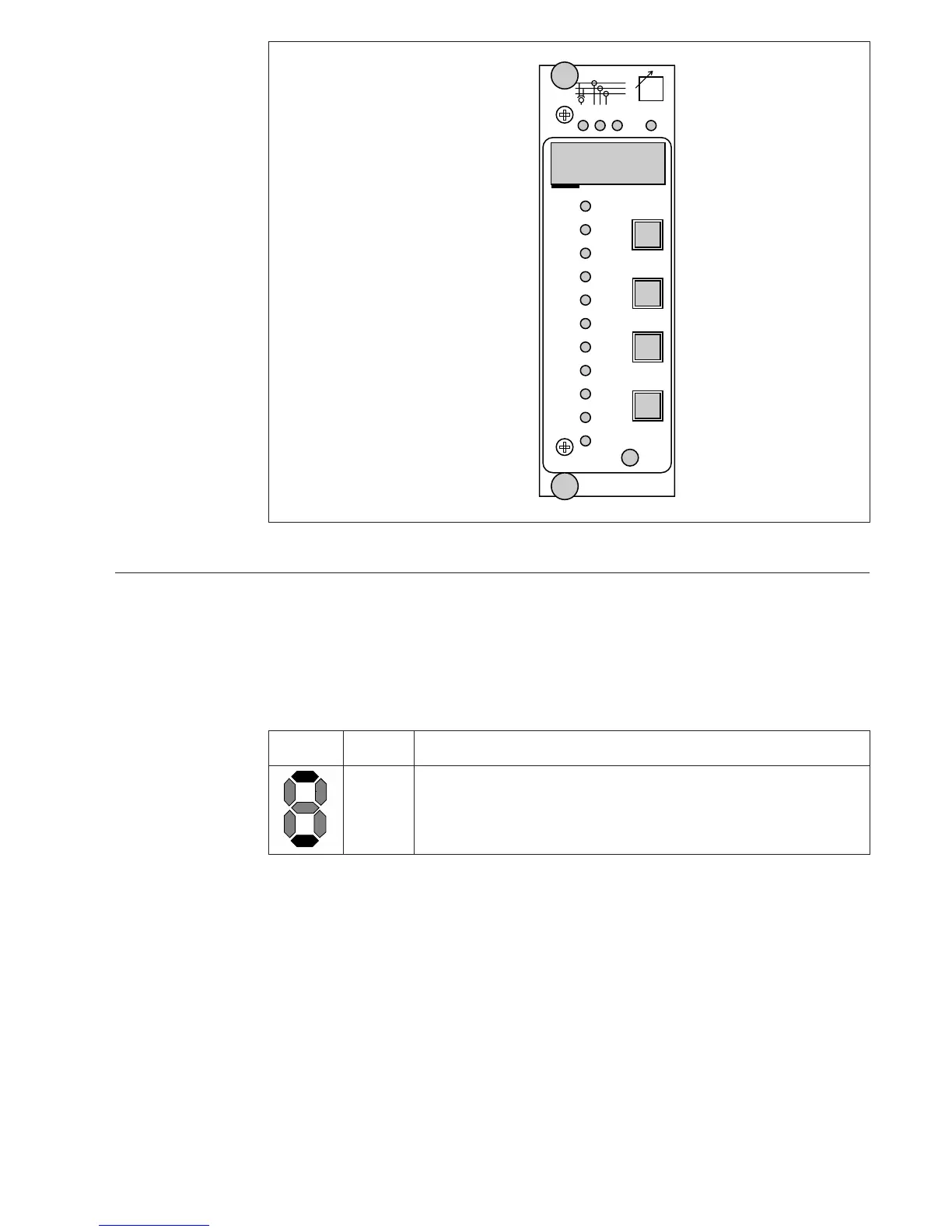
Front panel
Indicators for the measured voltage U
m
,
phase currents Im and voltage difference U
d
Indicator for reference voltage U
s
Indicator for bandwidth ∆U
s
Indicator for time delay T1
Indicator for time delay T2
Indicator for overcurrent blocking I>/I
n
Indicator for undervoltage blocking U</U
n
Indicator for overvoltage detection U>/U
n
Indicator for compensating parameter U
r
Indicator for compensating parameter U
x
Indicator for parallel operation
Indicator for manual operation
Device symbol
Indicator of the self-supervision
system
Digital display
Display step push-button/
Reset push-button
Program push-button
AUT/MAN push-button
Parallel operation push-button
Operation indicator
Type designation of the
regulator module
Fig. 2. Front panel of the automatic voltage regulating module SPCU 1D50.
Operation
indicators
When the voltage regulating module delivers a
raise or lower pulse, the yellow LED indicator
OUT in the bottom right corner of the front
panel is lit, and remains so as long as the pulse
is active. When the voltage U
m
is outside the
range defined by ∆U
s
, either the lower or the
raise delay counter is on. If U
m
> ∆U
s
(upper
limit), the bottom segment of the leftmost digit
starts flashing to indicate a lower pulse to come
after the set time delay. If U
m
< ∆U
s
(lower
limit), the top segment of the leftmost digit starts
flashing to indicate a raise pulse to come after
the set time delay.
Indicator Segment Explanation
raise Starts flashing, when the time delay of the raise pulse is running
lower Starts flashing, when the time delay of the lower pulse is running
Fig. 3. Start indications of the delay counter, when U
m
is selected to be presented.
 Loading...


