15
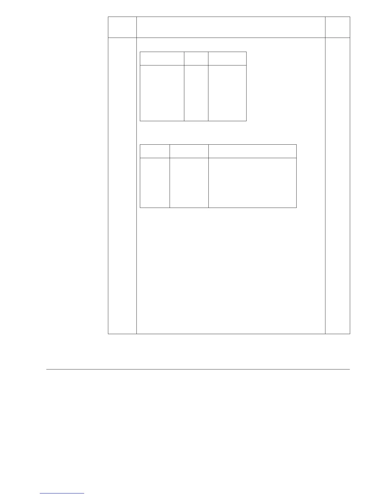
Register/ Recorded information Default
STEP setting
0 Display of external control signals
Value Input
First digit 1 Raise’
2 Lower’
Second digit 1 Auto’
2 Manual’
Third digit 1 Blocking
2 TCO
4 RSV
The TEST mode can be entered from register 0.
In this mode the output signals can be activated one by one:
Indicator Designation Output signal
O Us/Un U<, Undervoltage blocking
O ∆Us[%Un] U>, Overvoltage detection
O T1[s] I>, Overcurrent blocking
O T2[s] Lower
O I> /In Raise
O U</Un Aut/Man
A detailed description of the TEST mode is given in the manual
"General characteristics of D type relay modules".
A Address code of the regulator module, required for the communication
system. Register A contains the following subregisters:
1. Data communication rate of the module.
Selectable values 4.8 or 9.6 kBd. 9.6 kBd
2. Bus communication monitor. If the module is connected to a
communication system that is operating, the reading of the bus
communication monitor is 0, otherwise the numbers 0…255 are
rolling on the display.
3. Password needed for remote control of settings. 1
The password must always be entered (parameter V160) before a
setting can be altered via the serial communication.
4. Selection of main or second settings (V150). Main setting as default 0
setting.
Registers, address code of the relay module,
communication rate and password will not be
erased by a voltage supply failure. The setting
of the address code and the communication rate
is described in the manual "General character-
istics of D type relay modules".
Calibration
of voltage
measurement
The phase-to-phase voltage measurement U
m
can be calibrated by writing a measurement cor-
rection value to the serial parameter V176. The
permitted measurement correction range is -
5.00 to +5.00% of U
n
. If a certain input volt-
age is applied, and the measurement is corrected
with a positive value, the module will display a
voltage higher than that applied. If the meas-
urement is corrected with a negative value, the
module will display a lower value. The correc-
tion value is stored in the EEPROM and can-
not be erased by a supply voltage failure or by
formatting the EEPROM.
 Loading...


