5
Settings
All settings can be entered either via the front
panel push-buttons or over the serial commu-
nication.
The setting values are displayed by the right-
most three digits of the display. The left-most
digit shows, which setting value is indicated on
the display. How to locate the setting values with
the man-machine interface, is described in the
section "Menu chart".
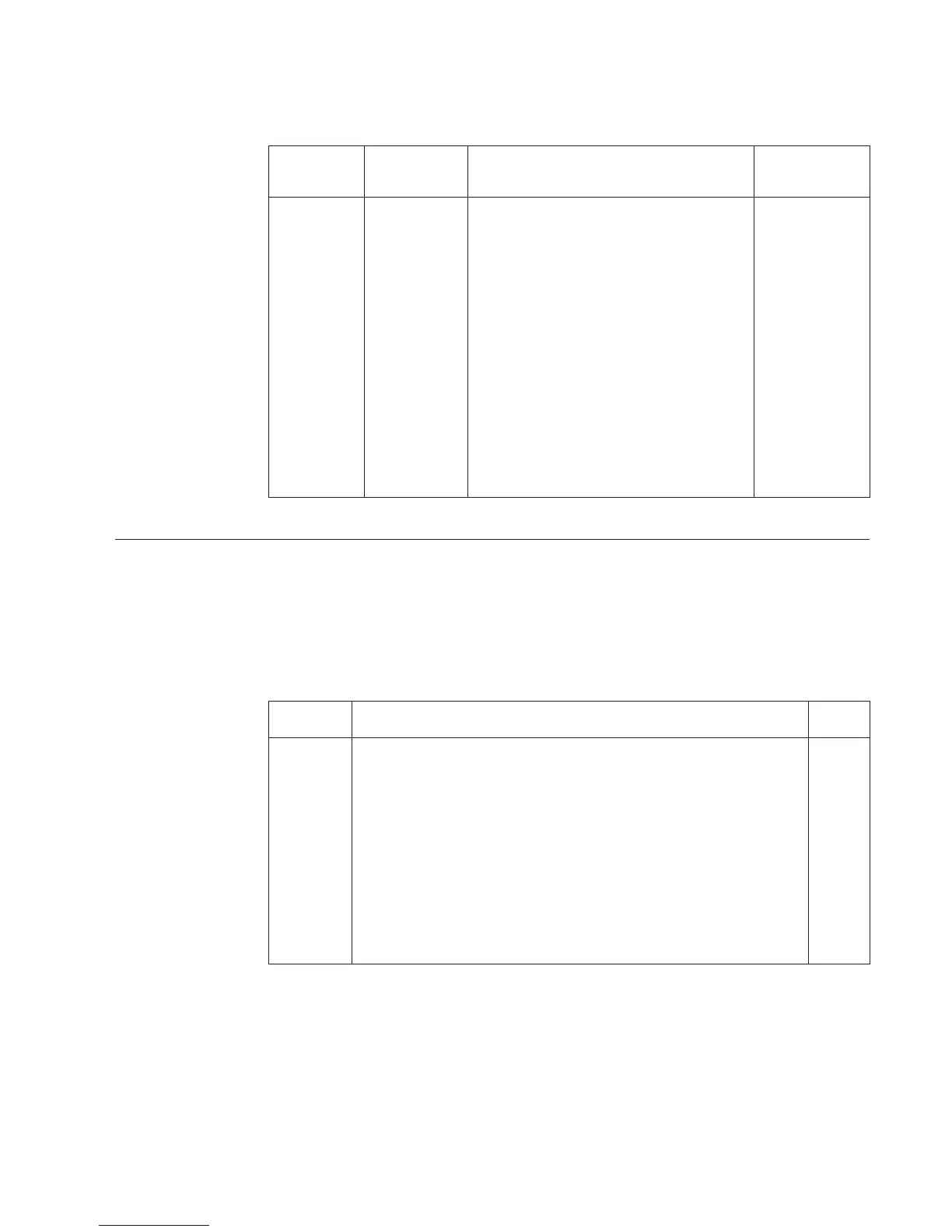
Register/ Setting Description Setting range/
STEP Default value
1 SGF1 Switchgroup, see section 0…255 /0
"selector switches" for further details
2 Tap position Low tap-changer position 0…34 /0
low
[1] Submenu Low level mA Current corresponding to the low tap- 0…20.0 mA /0
signal changer position
3 Tap position High tap-changer position 1…35 /35
high
[1] Submenu High level mA Current corresponding to the high tap- 0…20.0 mA /20
signal changer position
4 OPD Output pulse duration 0.5…10.0s /1.5
Settings for the serial communication is dealt with in the section "Recorded data".
Selector switches
The checksum of the programming switchgroup
SGF1 is indicated on the display, when the cor-
responding setting value is selected. An exam-
ple of calculating the checksum and detailed in-
formation of the push-button operations are
given in the general description of the D-type
SPC relay modules.
The number of the switches, 1...8, and the
switch positions, 0 and 1, are displayed during
the setting procedure. In normal service only
the checksum is displayed.
Switchgroup SGF1
Switch Function Default
SGF1/1..3 Not in use. 0
SGF1/4 Display mode 0
When SGF1/4=1, the display starts indicating the tap-changer position
continuously 5 min after the latest push-button operation.
When SGF1/4=0, the display turns dark 5 min after the latest push-
button operation.
SGF1/5...8 Not in use. 0
∑ SGF1 0
 Loading...


