Note: The figure and table exclusively show the thermal view of the complete sys-
tem. If additional space is required for operating or servicing the device, this must
be taken into account during installation.
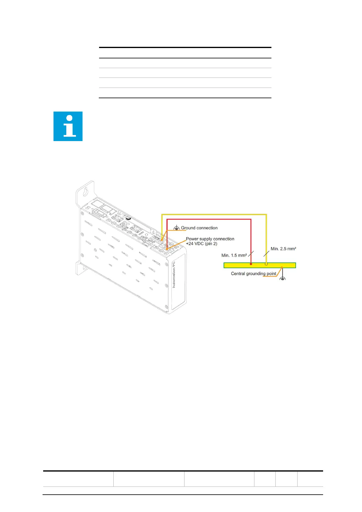
4.2.5 Electrical installation
The 3-pin connector required for connecting the power supply is delivered with the TGP. This can
also be ordered from B&R using model number 0TB103.9 (screw clamp terminal block) or 0TB103.91
(cage clamp terminal block).
The pinout is shown in the following table. The supply is protected internally by a soldered fuse (15
A, fast-acting) so that the device is not damaged under current overload conditions (fuse must be
replaced) or connected incorrectly (reverse polarity protection, fuse replacement not necessary). If
the fuse is destroyed during a fault event, the device must be replaced with a new TGP.
 Loading...