Operation Manual / TPL67-C.. - TPL71-C..
Page 7
© Copyright 2016 ABB. All rights reserved.
April 2016 HZTL2488_EN Revision C
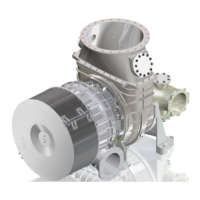
The turbocharger is a turbomachine and consists of the following main
components:
Turbine
Compressor
These are both mounted on a common shaft.
The exhaust gases from the diesel engine flow through the gas inlet cas-
ing (07) and nozzle ring (08) to the turbine wheel.
The turbine wheel (09) uses the energy contained in the exhaust gas to
drive the compressor wheel (12). The compressor then draws in fresh air,
compresses it and then forces it into the cylinders.
The exhaust gases escape to free air through an exhaust gas pipe which
is connected to the gas outlet casing (06).
The air which is necessary for operation of the diesel engine and is com-
pressed in the turbocharger is drawn through the suction branch or the fil-
ter silencer (01) into the compressor wheel (12). This air then passes
through the diffuser (11) and leaves the turbocharger through the com-
pressor casing (13).
The rotor runs in two radial plain bearings (02/05). One plain bearing is in
the bearing bush (04), and the second one is in the axial thrust bearing
(03) at the compressor end.
The plain bearings are connected to a central lubricating oil duct which is
fed with oil from the engine's lubricating oil circuit. The oil outlet is always
at the lowest point of the bearing casing (10).
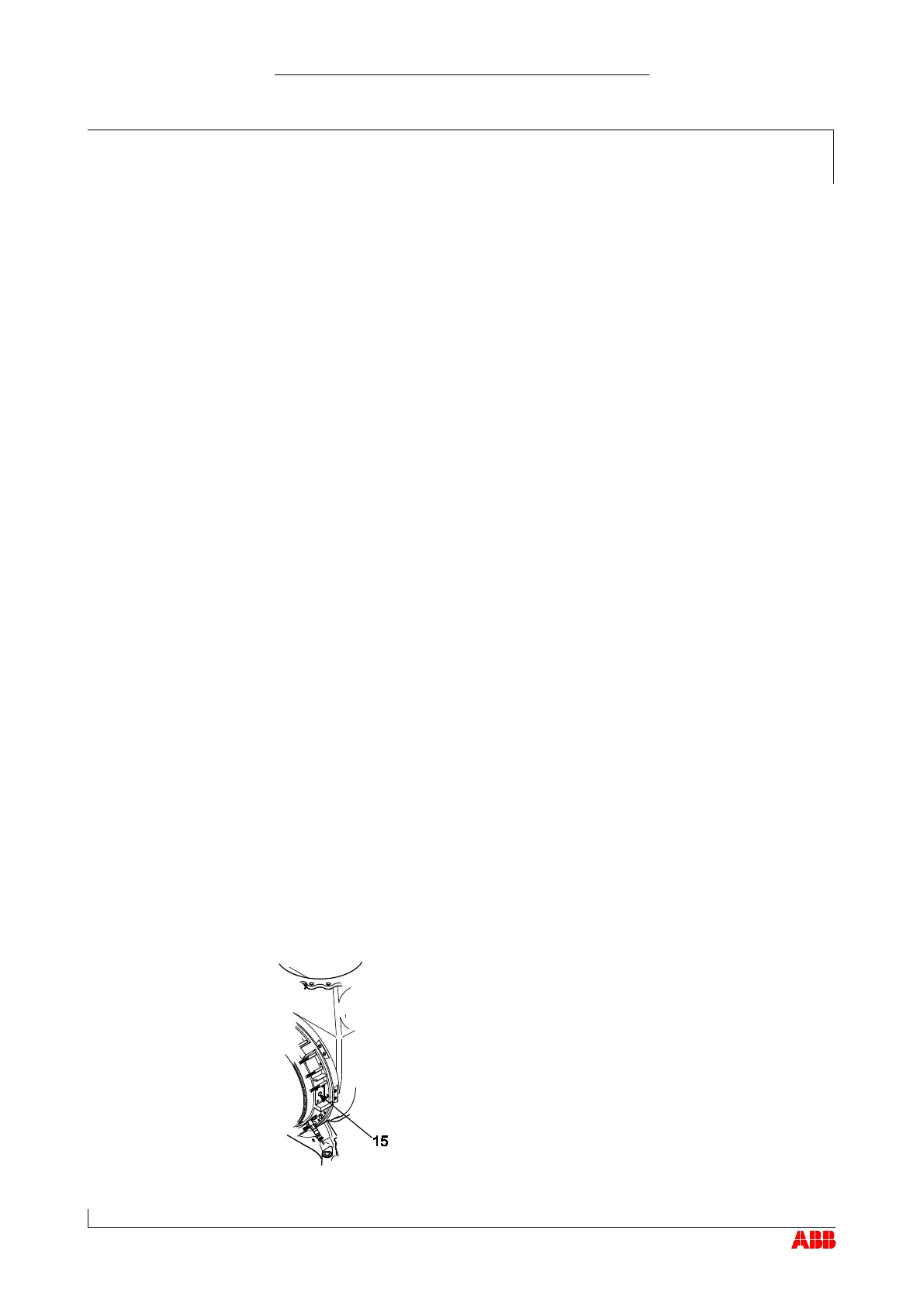
Turbocharger version with compressor wheel cooling system
Depending on its range of use, the turbocharger is provid-
ed with a compressor wheel cooling system. Compressor
wheel cooling means that, after the charge air cooler at the
engine end, cooled compressor air is delivered to the tur-
bocharger to cool the compressor wheel.
In view of the respective operating conditions, it is abso-
lutely essential that the compressor wheel is cooled in or-
der to guarantee its reliability and replacement intervals. In
the case of the turbocharger version with compressor
wheel cooling, the cooling air is supplied through the side
connection (15) in the bearing casing.
 Loading...