Table 4: Control wiring plug connector coding table
Panel rated current Revets position assembly in apparatus Hole open position in panel
B1
B2 B3
B4 B5 B6 B1 B2 B3 B4 B5
B6
1250A VD4 circuit breaker
0 0
1600A/2000A VD4 circuit breaker
0 0 0 0
2000A VD4 circuit breaker
0 0
2500A VD4 circuit breaker
0 0 0 0
1250A VD4 isolating truck
0 0 0
1600A/ 2000A VD4 isolating truck
0 0 0 0 0
2500A VD4 isolating truck
0 0 0 0
20 UNIGEAR ZS2 INSTALLATION, OPERATION AND MAINTAINANCE INSTRUCTION MANUAL
—
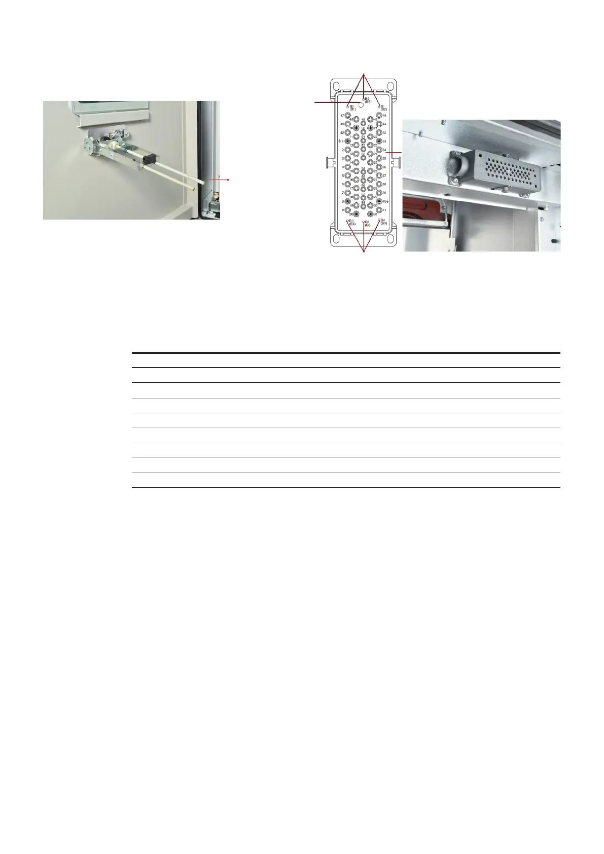
Figure 27 - Push button assembly for emergency ON/OFF arrangement
View of the push rod extension swung out by the knob at the front,
with the withdrawable Circuit breaker part in service position and the
door open
27.1
Swiveling
push rod
—
Figure 28 - Control wiring plug connector
1 Bore for actuating pin of the control wiring plug for
controlling the auxiliary switch
2,4 Centering striking tabs
3 Control wiring socket
2
1
4.5 Instructions for floor-rolling version
circuit breaker
In floor-rolling circuit breaker version, the circuit
breaker is mounted on a trolley equipped with
nylon wheels those roll on the ground, and
thereby making the handling of circuit breaker
easier.
The door of circuit breaker compartment and
cable compartment are unified to form a single
door, instead of two separate doors.
The circuit breaker compartment door is of
pressure resistant design for internal arc fault
and is also pad lockable. It is provided with
security glass for inspection purposes.
4.5.1 Handling of floor-rolling circuit breaker
4.5.1.1 Racking-in from Test to Service position
A ramp arrangement is provided in the
switchgear, as an integral part, to facilitate easy
insertion of the floor rolling circuit breaker into
switchgear; with the circuit breaker in switched
OFF condition. Refer Fig. 29.
The trolley must be pushed completely inside the
switchgear as far as possible, till the
Test position, and secured in place.
This is performed as follows:
• while pushing the circuit breaker, gently slide
handles of the traverse towards the square
spigot of the spindle mechanism at the center
of the circuit breaker
• on reaching the Test position of the circuit
breaker, release handles of the racking
mechanism or traverse
• locking flanges at both ends of the traverse
are to be aligned with slots provided on both
guide rails mounted on sidewalls of the
switchgear
Auxiliary power plug and socket with control
wiring are to be connected when the circuit
breaker is in Test/Disconnected position.
Manual insertion from the test/disconnected
position to the service position:
• Close the front door

 Loading...


