135
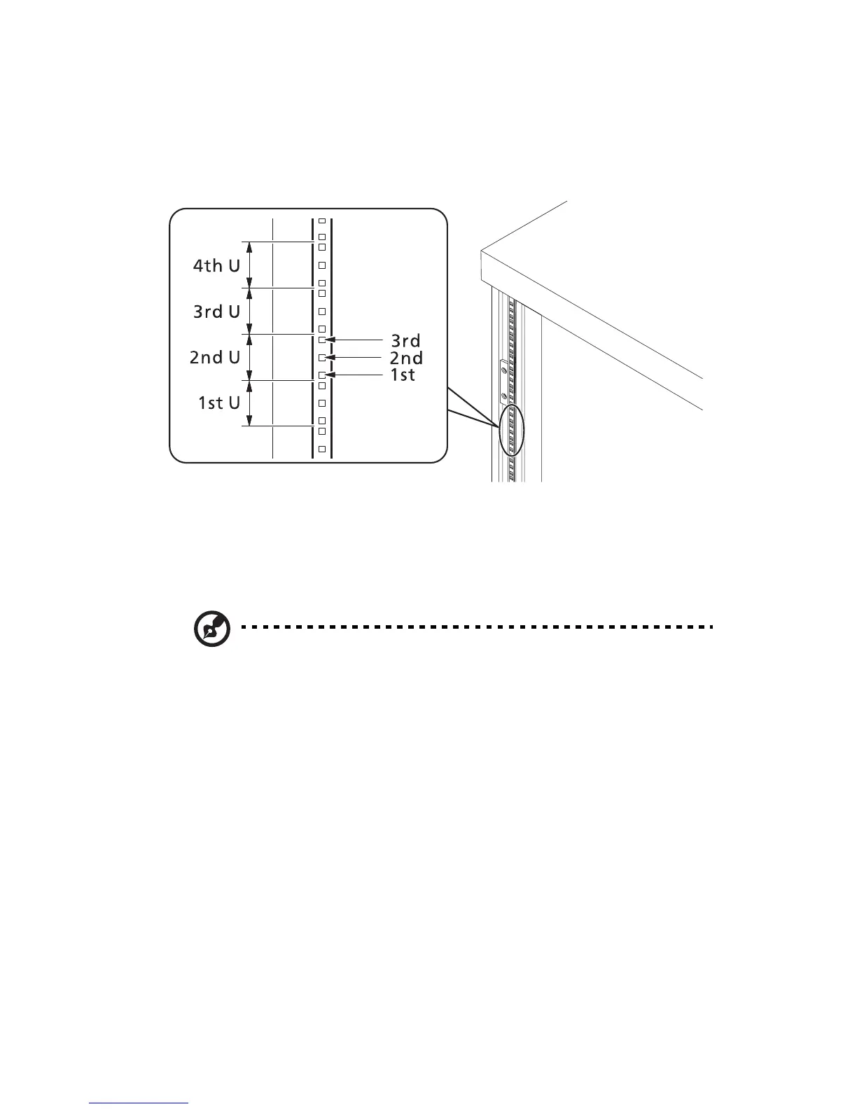
Vertical mounting hole pattern
The four vertical rails of the system rack contain mounting holes
arranged in a manner shown in the figure below:
The system occupies 1U in the rack. Count the U positions and hole
numbers from the bottom up.
The distance from the center of two holes with closer spacing to the
center of the next pair is equivalent to 1U.
Note: The unit of measurement used in this guide is "U"
(1U = 1.75 inches or 44.45 mm). The total sum of the heights of all
components in the rack measured in "U" cannot exceed the
height of the rack. For more information, refer to the
documentation that came with the system rack.
When installing components, you must start your measurement from
the center of the two holes with closer spacing. Otherwise, the screw
holes on the component may not match those on the rack.
 Loading...