3-22 Machine Maintenance Procedures
Circuit boards >10 cm² have been highlighted with a yellow rectangle as
shown in Figure 3-19. Remove the Circuit board and follow local
regulations for disposal.
Mainboard Installation 0
1. Put mainboard onto Base Assembly. Refer to Figure 3-16
2. Install and secure two (2) screws (F) to mainboard. Refer to Figure 3-17.
3. Connect Powerboard cable (G) and Speaker cable (H) to mainboard. Refer to
Figure 3-18.
4. Connect LVDS cable (D) and DC-in cable (E) to mainboard connector (Figure 3-17).
5. Put WLAN antenna (B) into the cable guides on the thermal module (Figure 3-17).
6. Connect WLAN antenna (B) to WLAN card (Figure 3-17).
7. Install HDD Module.
8. Install USB Module.
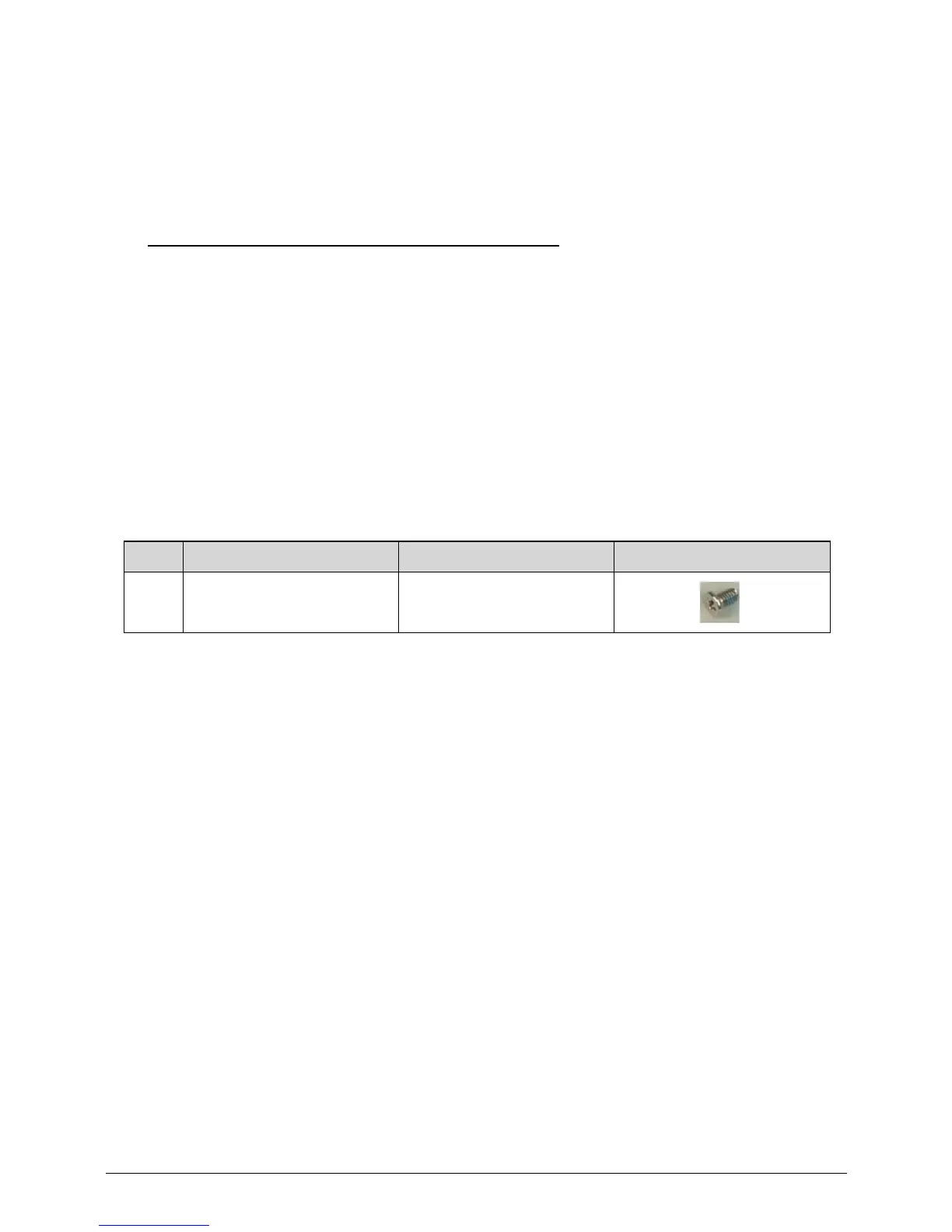
ID Size Quantity Screw Type
F M2.5*4.0 Ni 2
 Loading...