ICR-2701
2. Hardware Functionality
See Chapter 1.2 for the product hardware overwiew. Table 1 lists a short description of the
hardware, including the links to the chapters with a detailed description.
2.1 Ethernet Interfaces
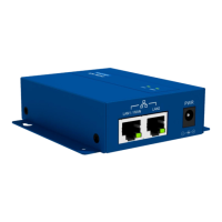
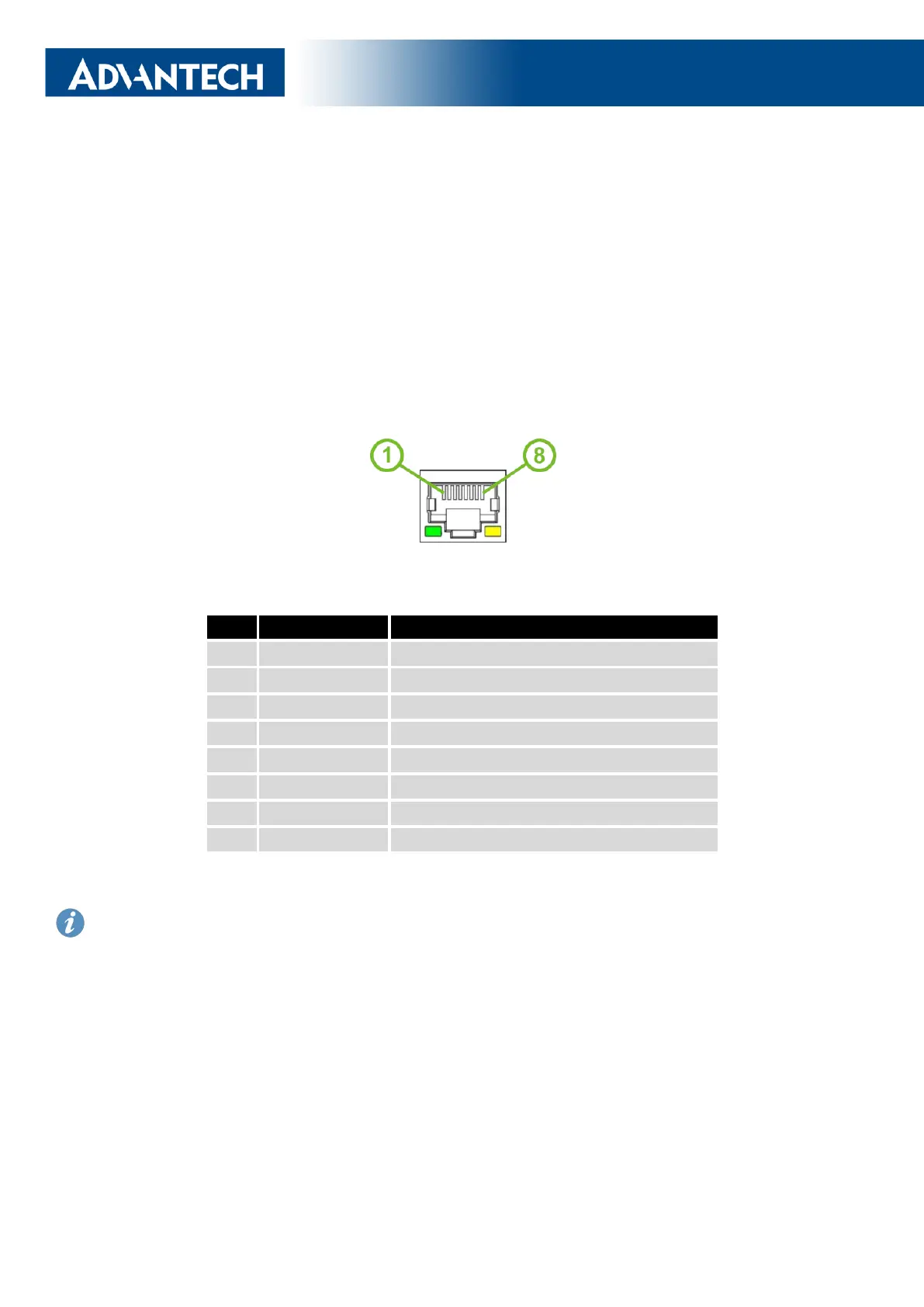
The panel socket of RJ45 is used for Ethernet interface. The pinout of the socket is shown
in Figure 1 and described in Table 3.
Figure 1: Ethernet Connector Pinout
Pin
Signal mark Description
1
TXD+ Transmit Data – positive pole
2
TXD- Transmit Data – negative pole
3
RXD+ Receive Data – positive pole
4
— —
5
— —
6
RXD- Receive Data – negative pole
7
— —
8
— —
Table 3: Ethernet Connector Pinout Description
The isolation barrier of the Ethernet ports against the ground is 1500 V.
12
 Loading...