ICR-2701
2.2 Power Supply
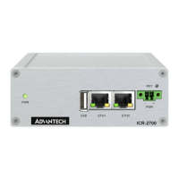
The pins of power supply are physically connected to the 6-pin terminal block panel socket
located on the left panel. The connection of power supply is shown in Figure 2 and described
in Table 4.
Figure 2: Connection of Power Supply
Pin
Signal mark Description
1
PWR(+) Positive pole of DC supply voltage (+9 to +48 V DC)
2
PWR(-) Negative pole of DC supply voltage
Table 4: Power Supply Pinout
Required power supply voltage for the router is between +9 V and +48 V DC, see the
connection scheme on Figure 2. Protection against reversed polarity without signaling is built
into the router. For correct operation it is necessary that the power source is able to supply
a peak current of 1 A.
Unit has to be supplied by a power supply specified as a Limited Power Source (LPS) or
CEC/NEC Class 2 source of supply.
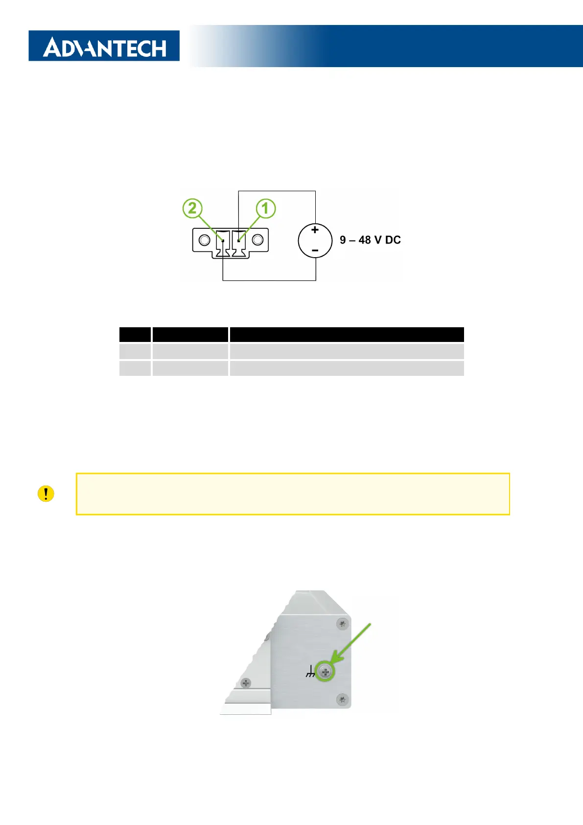
All metal parts of the router in a metal box, including the box itself, are connected with
the negative pole of the power supply (common pole). If recommended for the installation
environment, protect the router by grounding it properly by the grounding screw on the right
panel, see Figure 3.
Figure 3: Position of the Grounding Screw
13
 Loading...