ICR-2701
2.3 USB Port
There is one USB 2.0 host port with socket of USB-A type. USB Mass Storages and FTDI
serial converters are supported. For a piece of advice, how to fix an unsupported FTDI chip,
see the Commands and Scripts application note, chapter How to Use Unsupported FTDI Chip.
The USB port is disabled on overload to prevent its damage (connected device is trying to get
too high current). The port is enabled again after the reboot of the router.
Mounting USB Flash Drive to the System
It is necessary to mount the USB flash drive to be able to access it in the system of the
router. Follow these steps to mount the drive:
• Use the dmesg command to see the list of recently connected devices.
• In the output of the command find out the entry for the microSD card, for example:
sda: sda1
• To mount the card to to mnt directory, use the mount command:
mount /dev/sda1 /mnt
For more information about the commands for creating, mounting, checking and unmounting
a file system on a USB Flash Drive, see the application note for Ext4_tools router app.
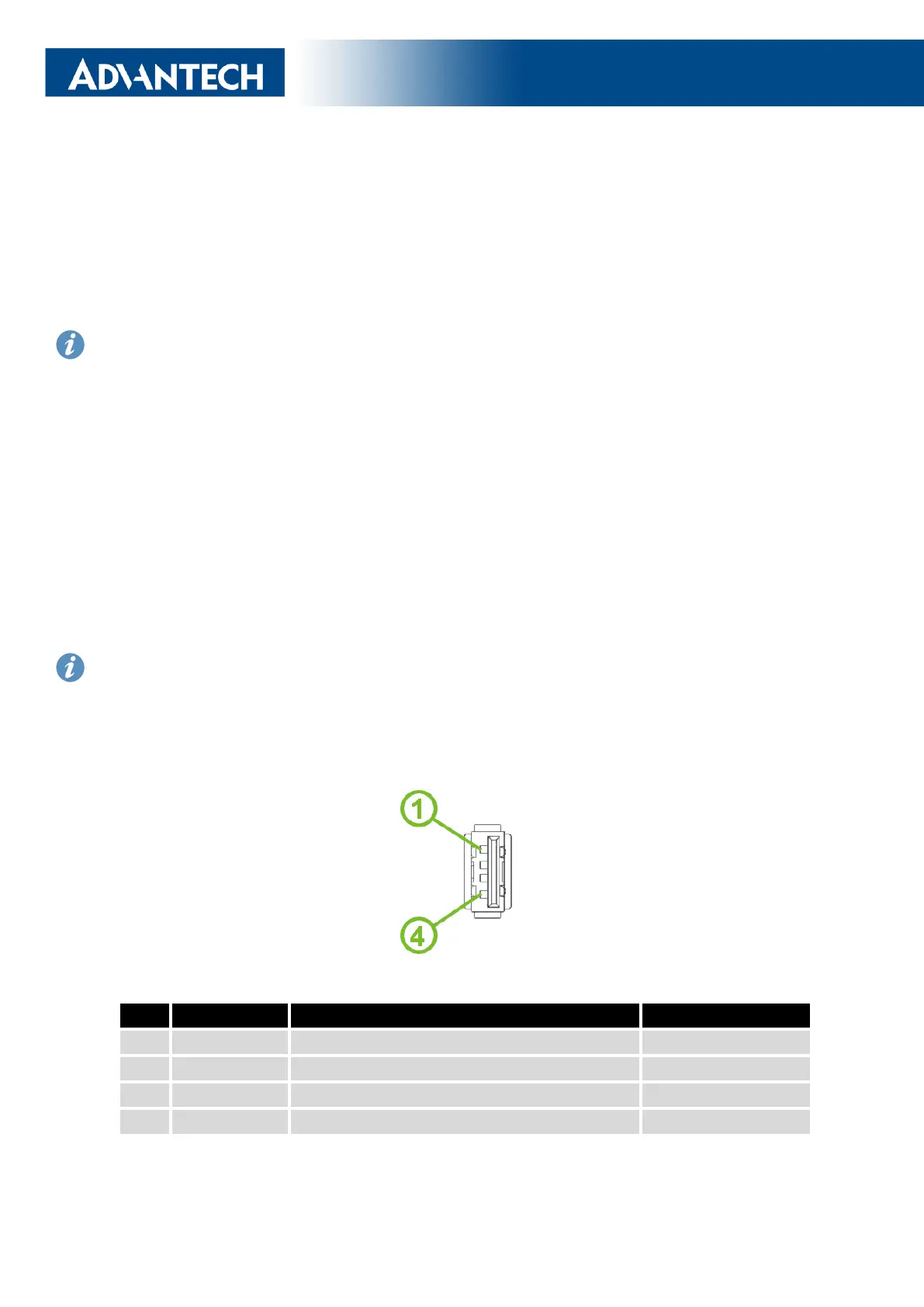
USB Socket Pinouts
USB socket pinouts is described in Figure 4 and Table 5.
Figure 4: USB Connector Pinnout
Pin
Signal mark Description Data flow direction
1
+5 V Positive pole of 5 V DC supply voltage, 0.5 A
2
USB data - USB data signal – negative pole Input/Output
3
USB data + USB data signal – positive pole Input/Output
4
GND Negative pole of DC supply voltage
Table 5: USB Connector Pinnout
14
 Loading...