ICR-3241
1.3 Hardware Overview
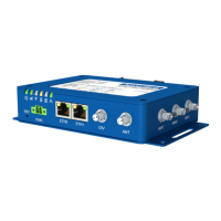
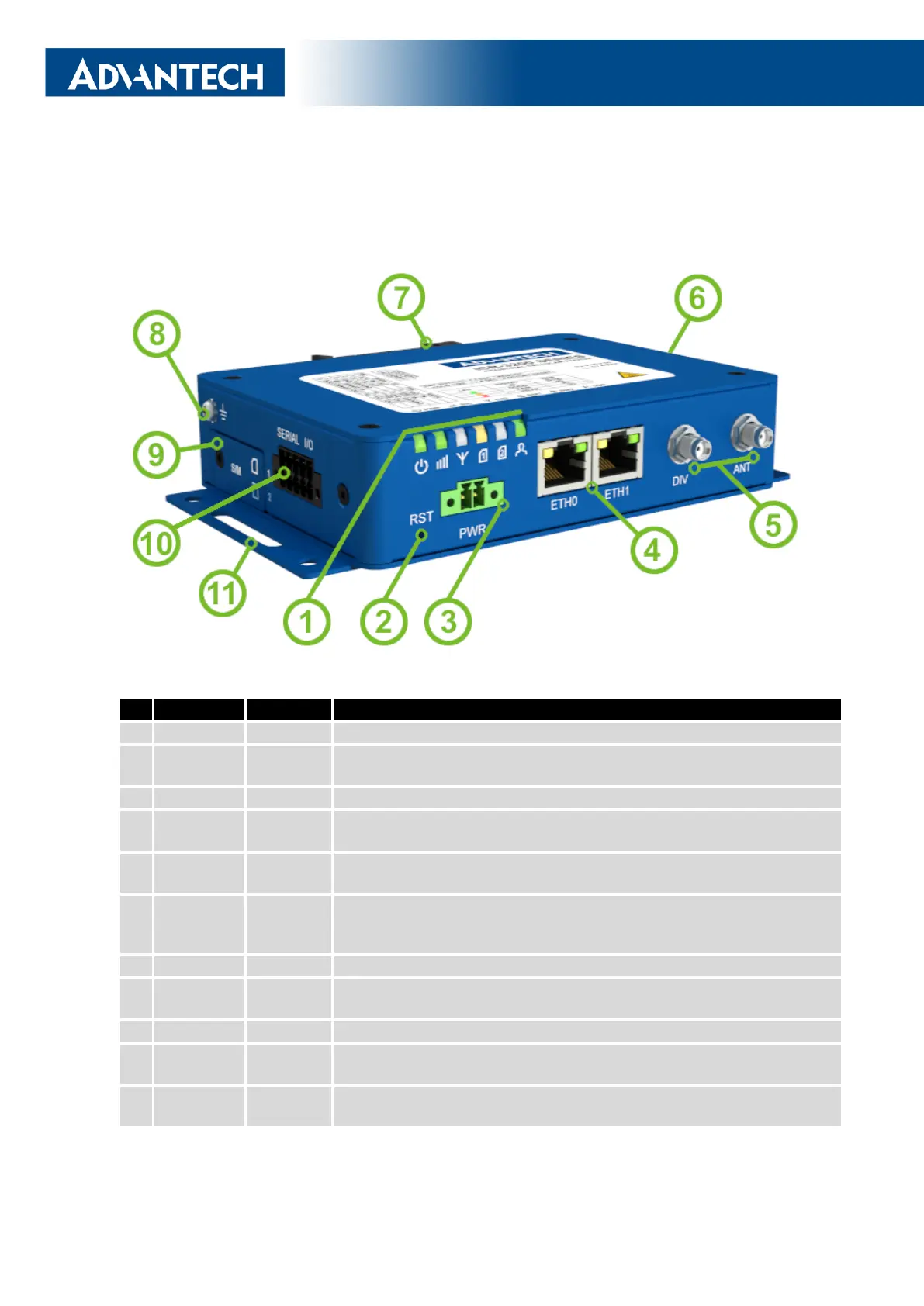
The router case preview is shown in Figure 5. A short description of hardware parts of the
router is listed in Table 1, including the links to the chapters with a detailed description.
Figure 5: Hardware Overview of the Router
# Item/CaptionType Description
1 LEDs - Status LED indication; see Chapter 2.7.
2 RST - Button to reboot the router or to restore the default
configuration; see Chapter 2.8.
3 PWR 2-pin Power supply 2-pin terminal socket; see Chapter 2.4.
4 ETH0,
ETH1
RJ45 100 MB Ethernet connection for the firts and second LAN; see Chap-
ter 2.3.
5 DIV, ANT SMA Connector for the diversity and main antennas of the cellular module;
see Chapter 2.2 and Chapter 4.4 for cellular module parameters.
6 WiFi,
GNSS
SMA,
R-SMA
One SMA connecor for the GNSS antenna and two R-SMA connectors
for the WiFi antennas. See Chapter 2.2 for more information, Chap-
ter 4.5 for GNSS parameters and Chapter 4.6 for WiFi parameters.
7 DIN clip - DIN rail clip, included as standard accessories; see Chapter 1.11.
8 Grounding
screw
M3 Pay attention to proper grounding; see Chapter 2.4.
9 SIM slots Mini SIM Two SIM card slots; see Chapter 2.1.
10 SERIAL |
I/O
10-pin
terminal
RS232, RS485, binary inputs, and binary outputs interfaces. See Chap-
ter 2.6 for more information.
11 Wall clips - Wall mounting clips, included as standard accessories; see Chap-
ter 1.10.
Table 1: Hardware Overview of the Router
5
 Loading...