168 Chapter 10
Command Reference
:DATA
:DATA
The function of this command when executed varies depending on the 1st parameter
specified as shown in the table below.
:DATA? {BUF1|BUF2|BUF3}
Syntax :DATA[:DATA]? {BUF1|BUF2|BUF3}
Description Reads out data in data buffer 1, data buffer 2 or data buffer 3. Executing this command
rewinds the pointer to the specified data buffer (the location to feed measurement data) to
the start. (Query only)
The transfer format of data read out with this command conforms to the setup made with
the :FORM command.
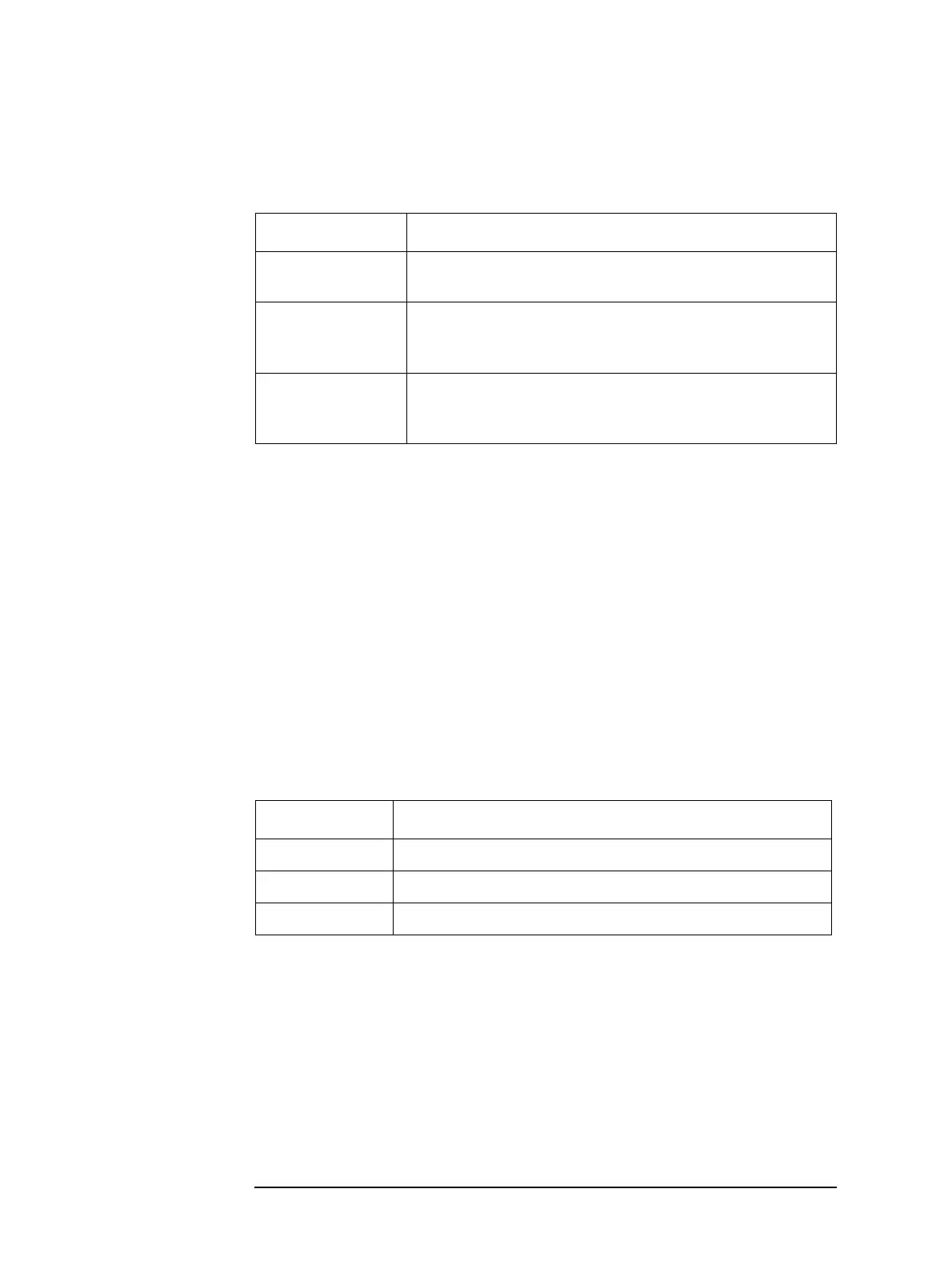
Parameters
1st parameter Function
BUF1, BUF2 or
BUF3
Reads out data in data buffer 1, data buffer 2, or data buffer 3.
For details, refer to :DATA? {BUF1|BUF2|BUF3} on page 168.
IMON or VMON Reads out the measured value of the current monitor or voltage
monitor. For details, refer to :DATA? {IMON|VMON} on
page 171.
REF1 or REF2 Sets or reads out the reference value of the primary parameter or
secondary parameter used in the deviation measurement mode.
For details, refer to :DATA {REF1|REF2} on page 172.
Description
BUF1 Reads out data in data buffer 1.
BUF2 Reads out data in data buffer 2.
BUF3 Reads out data in data buffer 3.