Setting Up the Oscilloscope
Digital probe lead set
1-20
Direct connection through 40-pin connector
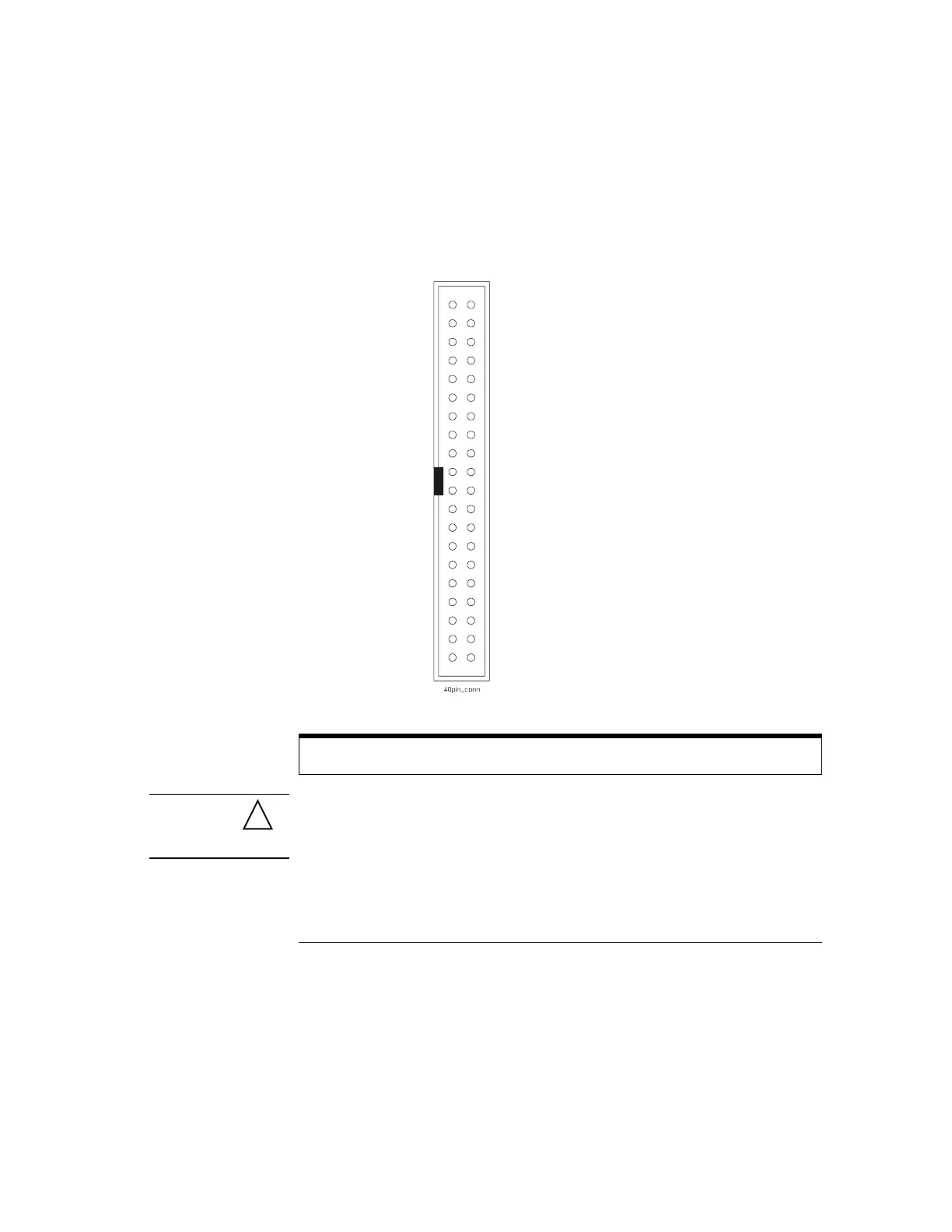
The probe cable can also be directly plugged into various 40-pin connectors on
circuit board under test. This requires each signal pin of the 40-pin connector
to have an isolation network (Figure 1-12) on the the circuit board. The pinout
of the 40-pin connector is shown in Figure 1-14.
Figure 1-14
40-pin Connector Pinout
CAUTION Do not exceed the maximum input voltage rating of ±40 V peak, CAT I. The
isolation network must be used on all digital channels for this to be valid.
Note: +5 V is supplied by the oscilloscope to provide power for the demo board. DO
NOT connect these pins to the circuit board under test.
D0
37
D1
35
D2
33
D3
31
D4
29
D5
27
D6
25
D7
23
D8
21
D9
19
D10
17
D11
15
D12
13
D13
11
D14
9
D15
7
Do not connect
5
Unused
3
+5 V (see note)
1
+5 V (see note)
39
38
36
34
32
30
28
26
24
22
20
18
16
14
12
10
8
6
4
2
40
Power Gn
Power Gn
Signal Gnd
Signal Gnd
Signal Gnd
Signal Gnd
Signal Gnd
Signal Gnd
Signal Gnd
Signal Gnd
Signal Gnd
Signal Gnd
Signal Gnd
Signal Gnd
Signal Gnd
Signal Gnd
Signal Gnd
Signal Gnd
Signal Gnd
Signal Gnd
!
 Loading...