Chapter 6: Replacing Assemblies
To remove and replace the front panel assembly
112
To remove and replace the front panel assembly
Use this procedure to remove and replace the front panel assembly. When necessary, refer to
other removal procedures. The graphics in this chapter are representative of the oscilloscope at
the time of this printing. Your unit may look different.
1
Disconnect the power cable and remove the top and bottom covers.
2 Remove the Auto-Probe assembly.
See “To remove and replace the AutoProbe assembly” on page 107..
3
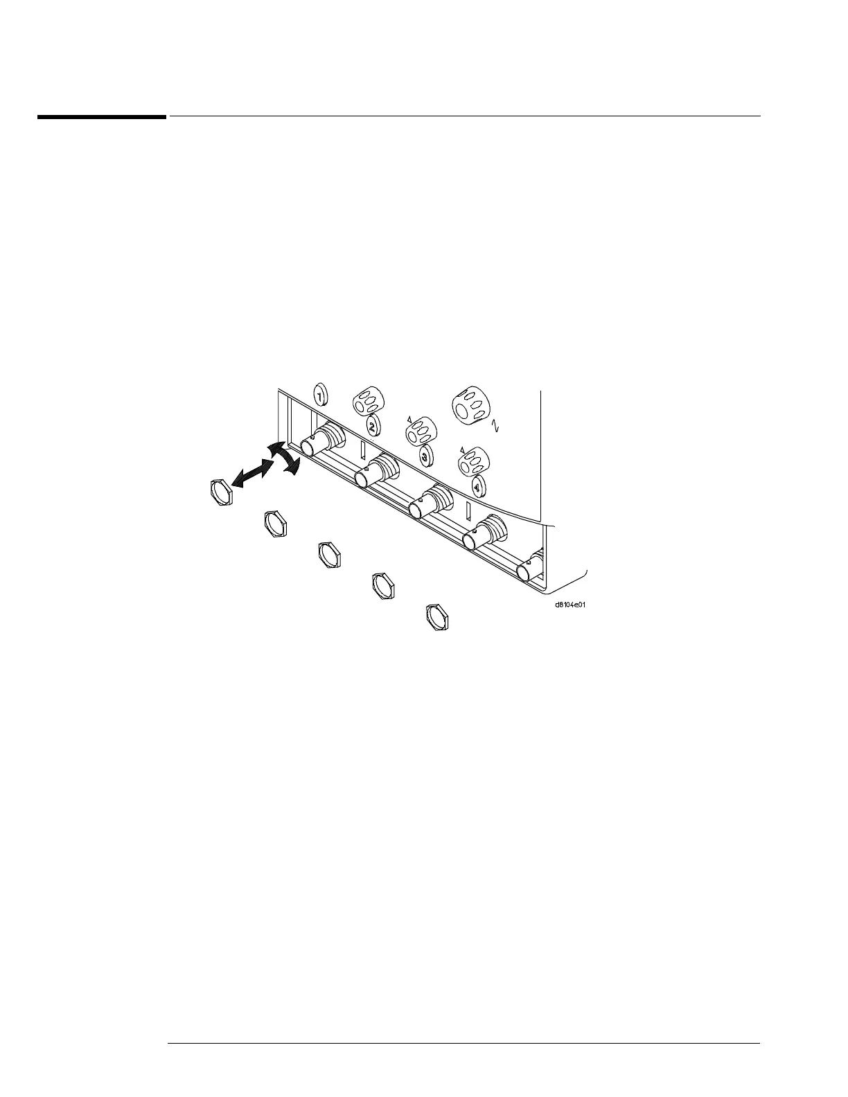
Using a 9/16” nut driver, remove the hex nuts that secure the BNC connectors to the
front panel.
When assembling the hex nuts to secure the BNC connectors to the front panel, put the conical
side of the nut toward the front-panel casting.
Figure 6-10
Removing the BNC nuts

 Loading...


