Chapter 6: Replacing Assemblies
To remove and replace the keyboard, touch screen, and flat-panel display assemblies
115
To remove and replace the keyboard, touch screen, and flat-panel
display assemblies
Use this procedure to disassemble and reassemble the keyboard, touch screen, and flat-panel
display. When necessary, refer to other removal procedures. The graphics in this chapter are
representative of the oscilloscope at the time of this printing. Your unit may look different.
1
Disconnect the power cable and remove the top and bottom cover.
2 Remove the front panel assembly from the chassis (see page 112).
3 Remove the ten Torx T10 screws that secure the front panel cover plate to the front
casting.
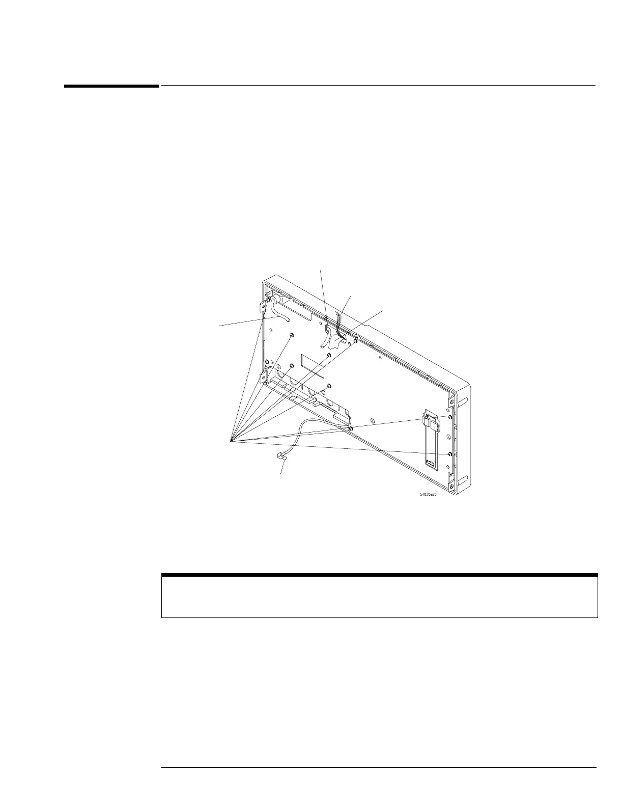
Figure 6-15
Front panel cover plate screws
4 Carefully feed the front-panel keyboard ribbon cable through the cable access hole
while separating the front panel cover plate from the front casting.
The display driver cable and touch screen USB cable remain attached to the cover plate.
Keep Long Screws Separate for Re-assembly
The four screws that fasten the keyboard to the front panel plate are longer than those around the perimeter
of the plate. Keep them separate for re-assembly.
Flat-panel display driver multi-
colored cable
T10 Screws (10)
Cal cable
Touch screen
USB cable
Keyboard ribbon
cable
Front panel
USB cable

 Loading...


