SELF TEST MODE
Note. If no buttons are pushed for a period of 60 seconds the test will terminate.
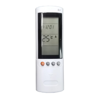
Enable self test mode. (Remote controller settings must be exactly as below).
STEP 1. Set the remote control to Heat mode, High FAN, set temperature 16
o
C, no I FEEL, Sleep or
any Timer settings set. Push the ON/OFF button and confirm the operate LED is on.
STEP 2. Cover the IR transmitter components in the head of the remote control so that it will not
transmit the changing signals to the indoor unit display. Change the remote control setting to Cool
mode, Low IFAN, no I FEEL Sleep or any Timer settings.
STEP 3. Uncover the remote control IR transmitter and change the temperature settings to send the
second setting to the unit’s receiver.
If the display/indoor unit receive the settings properly the unit is now in self test mode.
TEST 1. If in self test mode the LEDs will display the unit’s model as per the below table:-
Model Comp Operate LED Timer LED Filter LED
Portable. PS.
ON OFF OFF ON
GS Floor Console.
ON ON OFF OFF
WS026 & WS034.
ON ON OFF ON
Ducted. DS.
ON ON ON OFF
UA & K Cassette.
ON ON ON ON
WS042
OFF OFF ON OFF
SX Floor Console
OFF OFF ON ON
WS053-66. XLM17-24
OFF ON OFF ON
WS088-100. XLM30-36
OFF ON ON ON
STEP 4. Push the On/Off button to advance to the next test. Test will start immediately watch carefully.
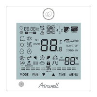
TEST 2. LED & Relay test.
All the LEDS will turn OFF. Then all the LEDS will turn ON for 1 second one by one in the following
sequence:-
Standby → Operate → Timer → Filter → Cool → Heat. (GS Floor Console is different).
Then all relays will turn ON one by one in the following sequence:-
Compressor → Outdoor fan → Reversing valve → Element 1 → Element 2 → Louvre motor →
Indoor fan low & Ionizer → Indoor fan med & Ionizer → Indoor fan high & Ionizer.
When the relay walk test is completed, the next test will start automatically, in 1 second.
TEST 3. Relay Frequency Zero Crossing Timing Test.
Pass:- All LEDs will be OFF. Fail:- If the frequency measuring process fails the Cool LED will be ON.
STEP 5. Press ON/OFF to advance.
TEST 4. Input test.
This stage is testing the thermistors, Level switch and clock terminals according the table below:-
LED indicator Condition for LED to be ON
Standby LED Room thermistor approx. = 25
o
C
Operate LED Indoor coil thermistor approx. = 25
o
C
Timer LED Outdoor coil thermistor approx. = 25
o
C
Filter LED Clock terminals are closed. (Time clock on).
Cool LED Float Switch Level 2 & 3. (Cassette only)
Heat LED Float Switch Level 4. (Cassette only)
Page 23
 Loading...