48 Rockwell Automation Publication 1420-UM001E-EN-P - March 2016
Appendix A PowerMonitor 500 Unit Data Tables
Geometric Representation of
Power and Power Factor
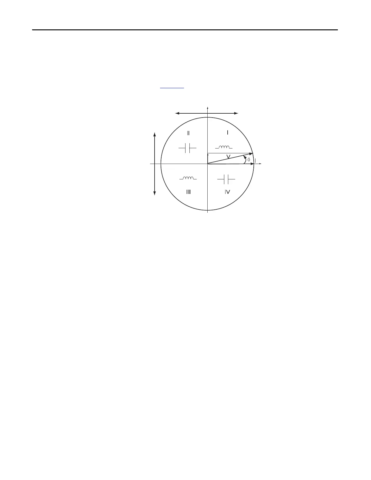
Power and power factor values are signed values in accordance with EN 62053
and as indicated in the diagram. Inductive or lagging power factor (Quadrant I
and III) is indicated by a positive power factor value. Capacitive or leading power
factor (Quadrant II and IV) is indicated by a negative power factor value. The
PowerMonitor™ 500 unit indicates the quadrant by using +/- L or +/- C as
shown in Figure 25
.
Figure 25 - Power and Power Factor Diagram
-W +W
Q
P
+VAR
-VAR
PF > 0, ‘-L’ PF < 0, ‘C’
PF > 0, ‘L’PF < 0, ‘-C’
- W = Exported real power
+ W = Imported real power
+ VAR = Imported reactive
power
- VAR = Exported reactive
power
 Loading...


