Rockwell Automation Publication CNET-IN005A-EN-P - May 2011 23
Install a 1768 ControlNet Communication Module Chapter 2
Installation Summary
To install a communication module in a 1768 ControlLogix chassis, complete
these steps.
1. Set the Node Address
.
2. Install the Module
.
3. Connect the Module to a ControlNet Network
.
4. Remove the Module
.
Grounding Considerations
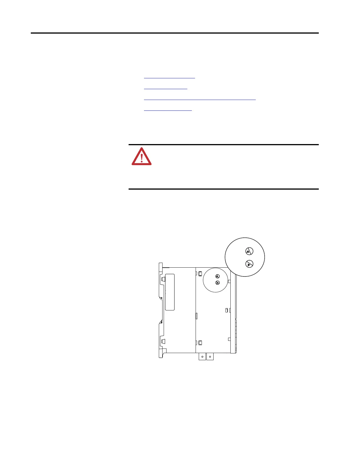
Set the Node Address
Use a small screwdriver to set the module’s node address switches. You must
specify a unique ControlNet node address. You can select an address of 01…99.
Address 00 is an invalid ControlNet node address.
ATTENTION: This product is grounded through the DIN rail to chassis
ground. Use zinc-plated yellow-chromate steel DIN rail to assure proper
grounding. The use of other DIN rail materials (for example, aluminum or
plastic) that can corrode, oxidize, or are poor conductors, can result in
improper or intermittent grounding. Secure DIN rail to mounting surface
approximately every 200 mm (7.87 in.) and use end-anchors appropriately.
NETWORK
ADDRESS
31651- M
50
60
6
8
7
70
9
0
4
3
2
1
5
80
90
00
10
20
30
40
NETWORK
ADDRESS
50
60
6
8
7
70
9
0
4
3
2
1
5
80
90
00
10
20
30
40
Top of Module
Back of Module
This module’s node address is 21.
 Loading...

