Rockwell Automation Publication 1769-UM021G-EN-P - October 2015 51
Install the CompactLogix 5370 L2 Controller Chapter 2
Complete these steps to connect power to the CompactLogix 5370 L2
control system.
1. Verify that the external 24V DC power source is not powered.
2. Mount the external 24V DC power source on a DIN rail.
The external 24V DC power source can be installed on the same DIN rail
as the controller or a separate DIN rail.
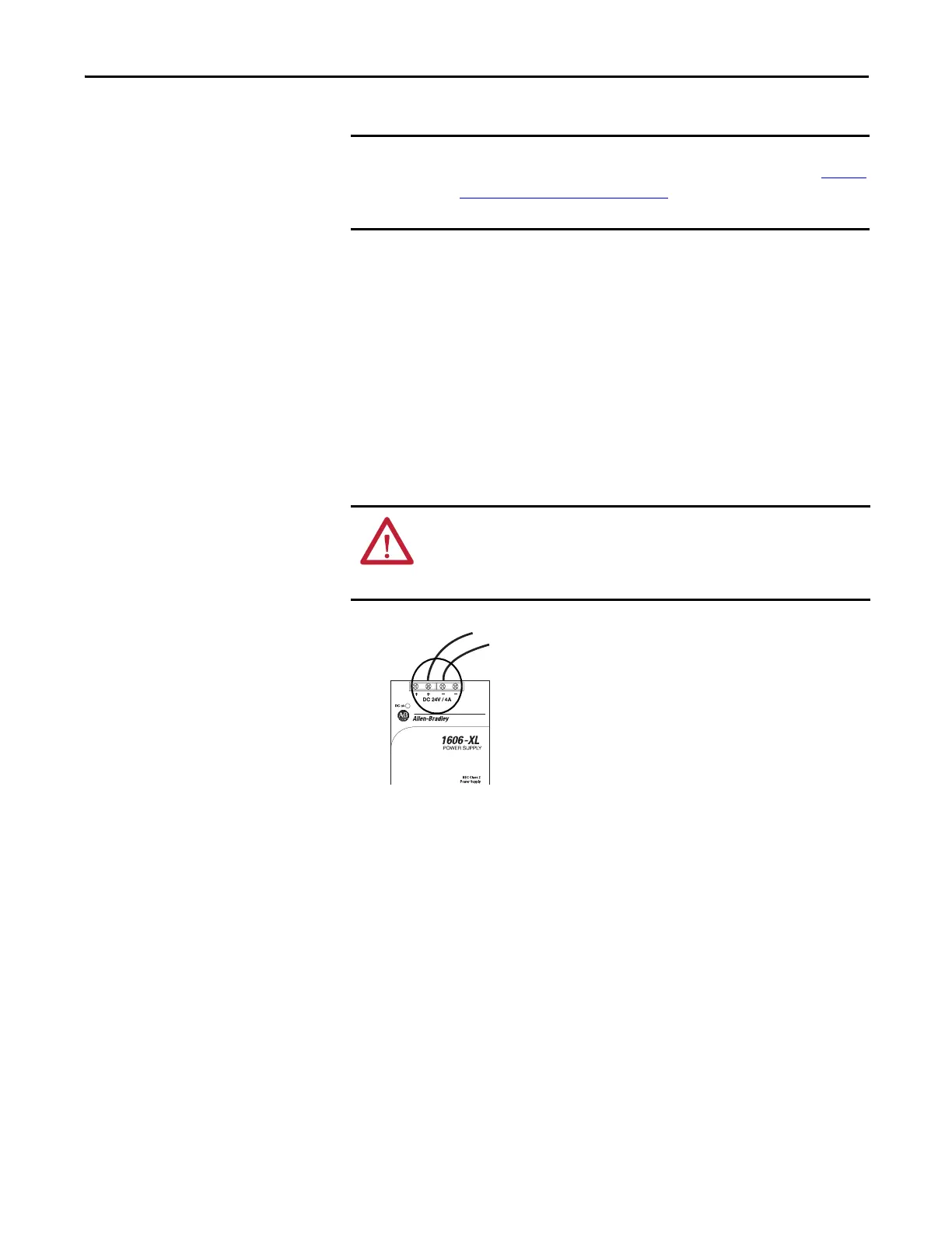
3. Connect wires to the 24V DC+ and 24V DC- connections on the external
24V DC power source.
4. Strip 8 mm (0.31 in) insulation from the end of the wire that you connect
to the +24VDC terminal on the controller.
The 1606-XLDNET4 power supply is not certified for use in all applications, for
example, you cannot use it in hazardous locations. Read the points in Connect
Power to the Control System on page 50 before choosing the external power
supply for your application.
WARNING: If you connect or disconnect wiring while the field-side power is on,
an electrical arc can occur. This could cause an explosion in hazardous location
installations. Be sure that power is removed or the area is nonhazardous before
proceeding.
 Loading...

