52 Rockwell Automation Publication 1769-UM021G-EN-P - October 2015
Chapter 2 Install the CompactLogix 5370 L2 Controller
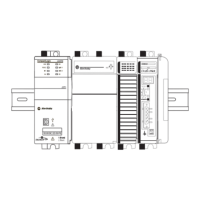
5. Connect the wire from the 24VDC+ terminal on the external 24V DC
power source to the +24VDC terminal on the controller.
6. Strip 8 mm (0.31 in) insulation from the end of the wire that you connect
to the COM terminal on the controller.
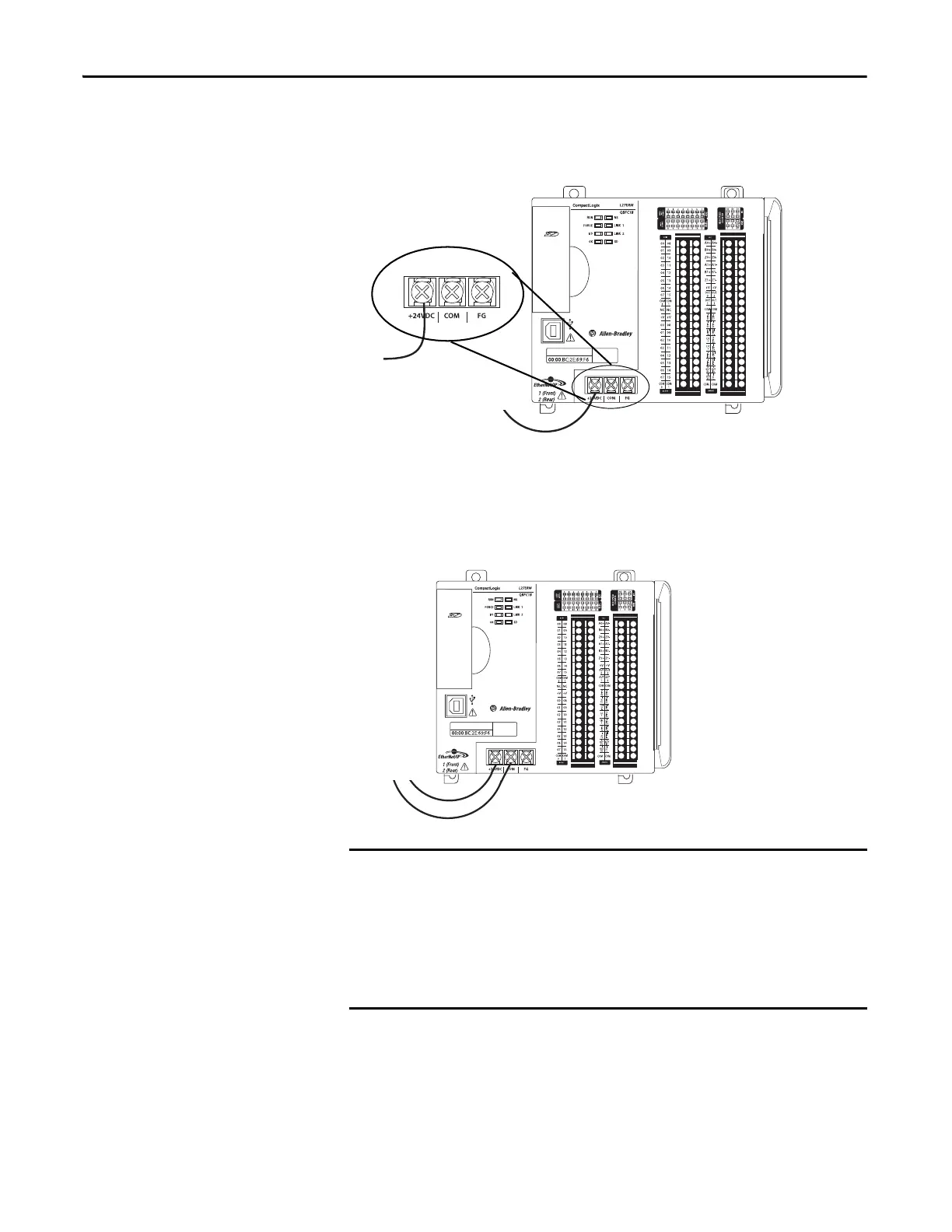
7. Connect the wire from the 24V DC- terminal on the external 24V DC
power source to the COM terminal on the controller.
If your application requires a power control device, for example, a switch or
relay, between the external power supply and the embedded power supply of
the CompactLogix 5370 L2 controller to control when the controller is powered,
you must install the power control device at the +24V DC terminal on the
controller.
If you install the power control device at the COM terminal, the
CompactLogix 5370 L2 controller cannot power up or power down properly.
 Loading...

