10 1769-L20, 1769-L30 CompactLogix™ Controllers
Publication 1769-IN047C-EN-P - April 2003
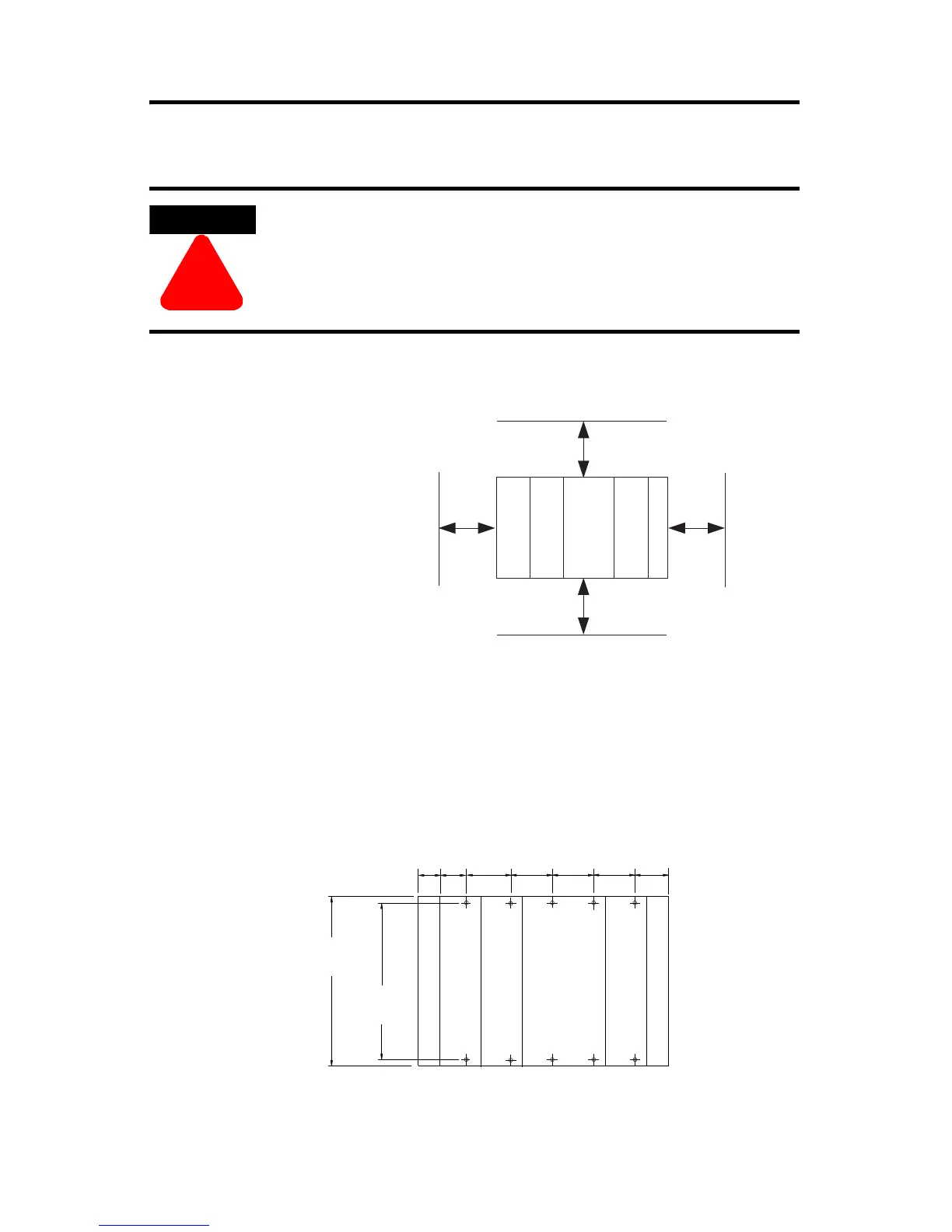
Mount the System
Minimum Spacing
Maintain spacing from
enclosure walls,
wireways, adjacent
equipment, etc. Allow 50
mm (2 in.) of space on all
sides, as shown. This
provides ventilation and
electrical isolation.
Panel Mounting
Mount the controller to a panel using two screws per module. Use M4 or #8
panhead screws. Mounting screws are required on every module.
Panel Mounting Using the Dimensional Template
ATTENTION
!
During panel or DIN rail mounting of all devices, be sure that
all debris (metal chips, wire strands, etc.) is kept from falling
into the controller. Debris that falls into the controller could
cause damage while the controller is energized.
Bottom
Side Side
Top
CompactLogix
Controller
Power Supply
Compact I/O
Compact I/O
End Cap
50 mm
50 mm
50 mm
50 mm
35
(1.38)
35
(1.38)
132
(5.197)
122.6±0.2
(4.826±0.008)
35
(1.38)
28.5
(1.12)
25
(.985)
15
(.590)
35
(1.38)
CompactLogix Controller
Power Supply
Compact I/O
Compact I/O
End Cap
NOTE: All dimensions are in mm (in.).
Hole spacing tolerance: ±0.4 mm (0.016 in.)
battery door
 Loading...


