1769-L20, 1769-L30 CompactLogix™ Controllers 13
Publication 1769-IN047C-EN-P - April 2003
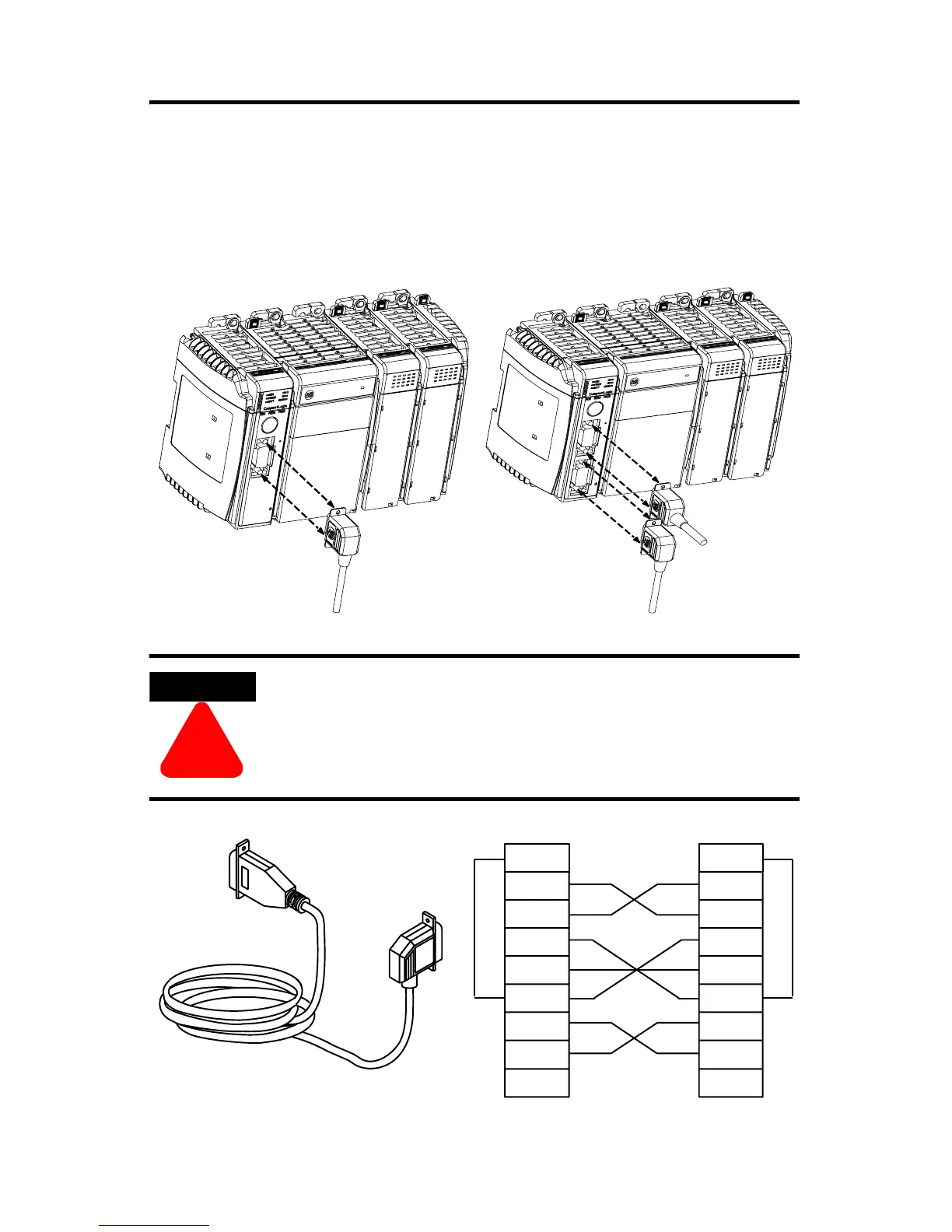
RS-232 Connections to the Controller
The following illustrations show which cables can be used to connect to the
controller. To connect two cables to the 1769-L30 controller, you must connect the
straight cable end to Channel 0.
ATTENTION
!
When you connect or disconnect the serial cable while
backplane power is on, an electrical arc can occur. In
hazardous locations, this could cause an explosion.
NOTE: The Channel 0 port is locally
grounded. Only Channel 1 of the 1769-L30
controller is electrically isolated.
1769-L20 controller 1769-L30 controller
2 RDX
3 TXD
4 DTR
COMMON
6 DSR
7 RTS
8 CTS
9
1 CD
2 RDX
3 TXD
4 DTR
COMMON
6 DSR
7 RTS
8 CTS
9
1 CD
1747-CP3 or 1756-CP3
9-pin, male D-shell straight
cable end
9-pin, female D-shell
right-angle cable end
straight cable end
right-angle cable end
This cable must be shielded and tied to the connector
housing.
 Loading...


