1769-L20, 1769-L30 CompactLogix™ Controllers 9
Publication 1769-IN047C-EN-P - April 2003
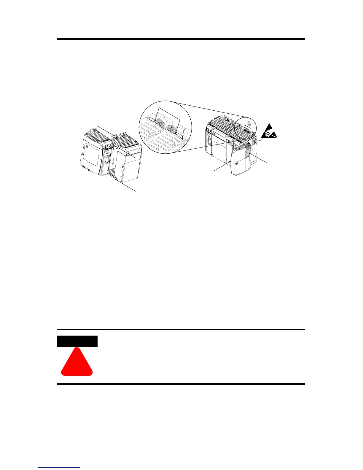
Assemble the System
The controller can be attached to an adjacent I/O module or power supply before
or after mounting. For mounting instructions, see
“Panel Mounting” on page 10, or
“DIN Rail Mounting” on page 11.
1. Disconnect line power.
2. Check that the lever of the adjacent module (A) is in the unlocked (fully
right) position.
3. Use the upper and lower tongue-and-groove slots (B) to secure the modules
together.
4. Move the module back along the tongue-and-groove slots until the bus
connectors line up with each other.
5. Use your fingers or a small screwdriver to push the module’s bus lever back
slightly to clear the positioning tab (C).
6. Move the module’s bus lever fully to the left (D) until it clicks. Ensure it is
locked firmly in place.
7. Attach an end cap terminator (E) to the last module in the system by using
the tongue-and-groove slots as before.
8. Lock the end cap bus terminator (F).
ATTENTION
!
When attaching the controller, power supply, and I/O
modules, it is very important that the bus connectors are
securely locked together to ensure proper electrical
connection.
F
E
D
C
B
B
A
 Loading...


