6 1769-L20, 1769-L30 CompactLogix™ Controllers
Publication 1769-IN047C-EN-P - April 2003
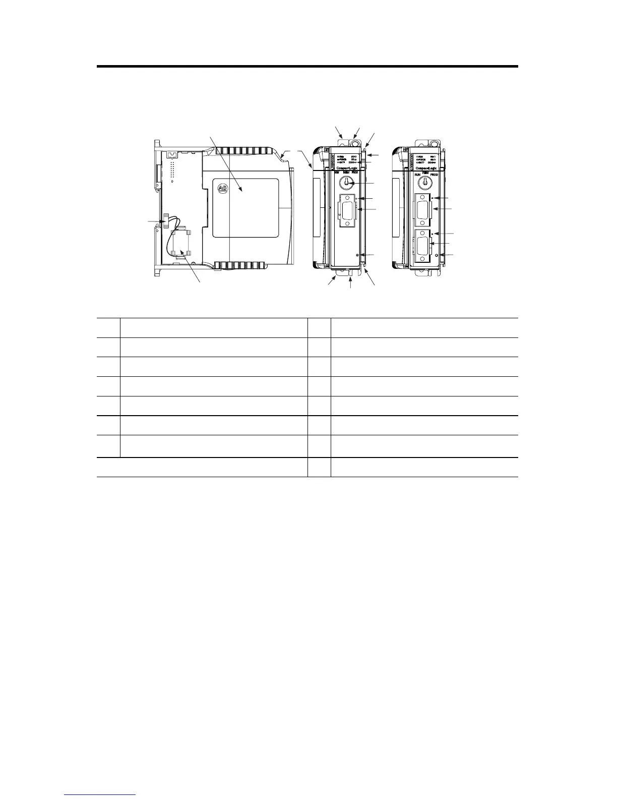
CompactLogix Controller Description
System Planning
Consider the following when planning your CompactLogix system:
· The CompactLogix controller is always the left-most module in the system.
· The controller must be located within four modules of the system power
supply. Some I/O module’s may be located up to 8 modules away from the
power supply. See the documentation for your 1769 I/O modules for details.
· The 1769-L20 controller supports up to 8 I/O modules in a maximum of 2
I/O banks (1 expansion cable allowed).
· The 1769-L30 controller supports up to 16 I/O modules in a maximum of 3
I/O banks (2 expansion cables allowed).
· Each I/O bank requires its own power supply.
· Only one controller can be used in a CompactLogix system.
· A 1769-ECR (right end cap) or 1769-ECL (left end cap) is required to
terminate the end of the communication bus.
1 DIN rail latch 8 Channel 0 RS-232 Port
2 panel mounting tab 9 Channel 0 default communication push button
3 tongue and groove slots 10 Channel 1 RS-232 Port
4 stationary bus connector 11 Channel 1 RS-232 Port Status LED
5 status LEDs 12 battery door
6 key switch 13 battery door label
7 Channel 0 RS-232 Port Status LED 14
battery
(1)
(1) See Connect the Battery on page 8 for the actual position of the battery.
15 battery connector
1
1
2
2
3
3
4
5
6
7
8
7
8
9
9
10
14
15
12
13
11
1769-L20 controller 1769-L30 controller
 Loading...


