Rockwell Automation Publication 193-IN080A-EN-P - September 2018 5
E300 Electronic Overload Relay
What You Need
• E300 relay control, communication, and sensing modules
• Any additional modules required (operator station, contactor, etc.)
• Wiring diagram
• Thin flathead screwdriver
• Wire for I/O terminals, #12…24 AWG
• Standard industrial grade Ethernet or DeviceNet™ cable
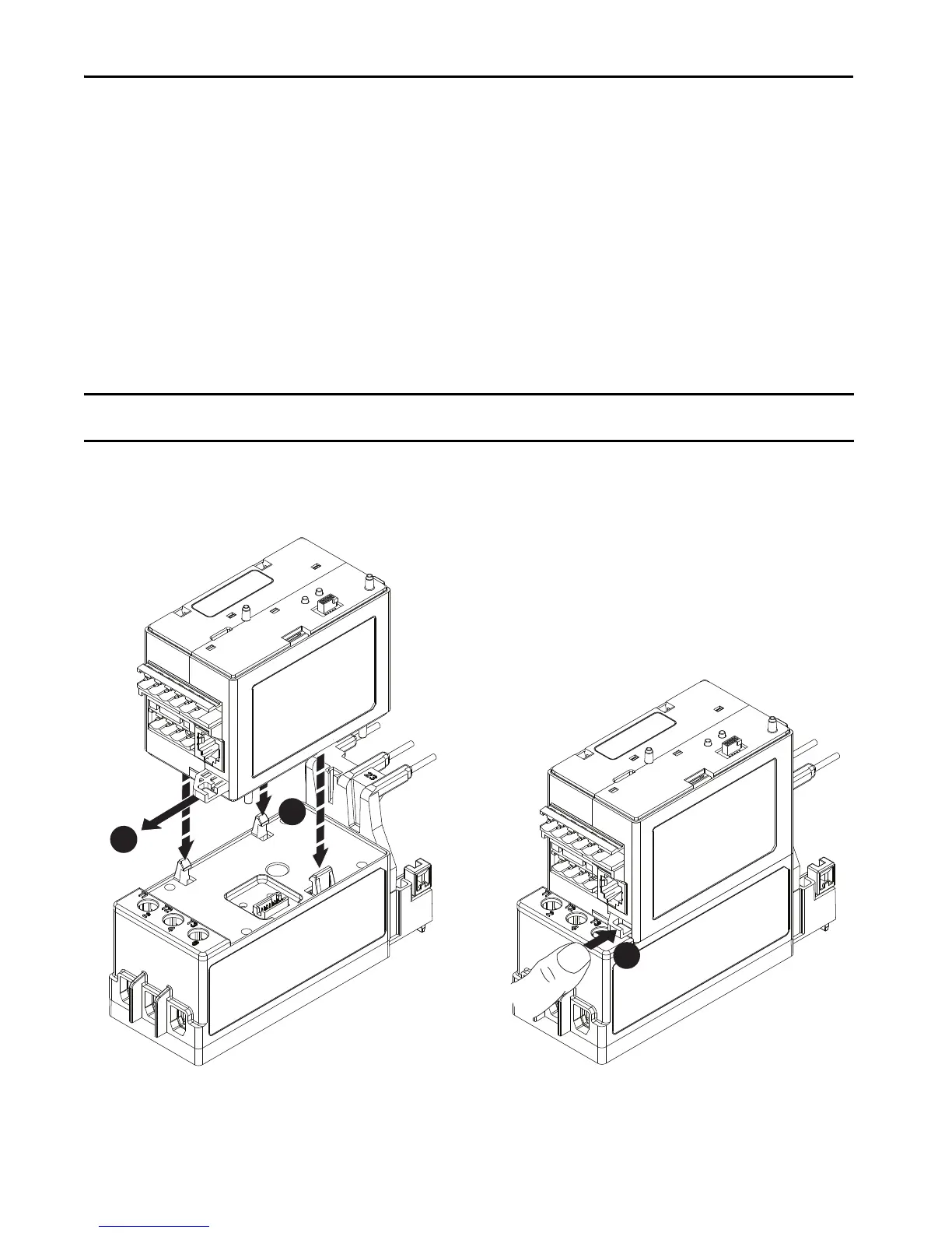
Assemble the E300 Relay
Complete the following steps to assemble the E300 relay. When you have finished, you will be ready to wire and configure the device.
1. Connect the E300 relay control module to the E300 relay sensing module.
Be sure to secure this connection by pushing in the tab on the right side of the control module.
IMPORTANT
Take caution while assembling each module and add-on component. Small I/O pins can bend and/or break, which causes a module service error once the
device is configured.

 Loading...


