Rockwell Automation Publication 842E-UM001C-EN-P - September 2016 39
Chapter 4
Installation
Mechanical
This chapter describes how to install the 842E EtherNet/IP Encoder.
Also refer to the installation sheet provided in the box, Publication No.
100000169360.
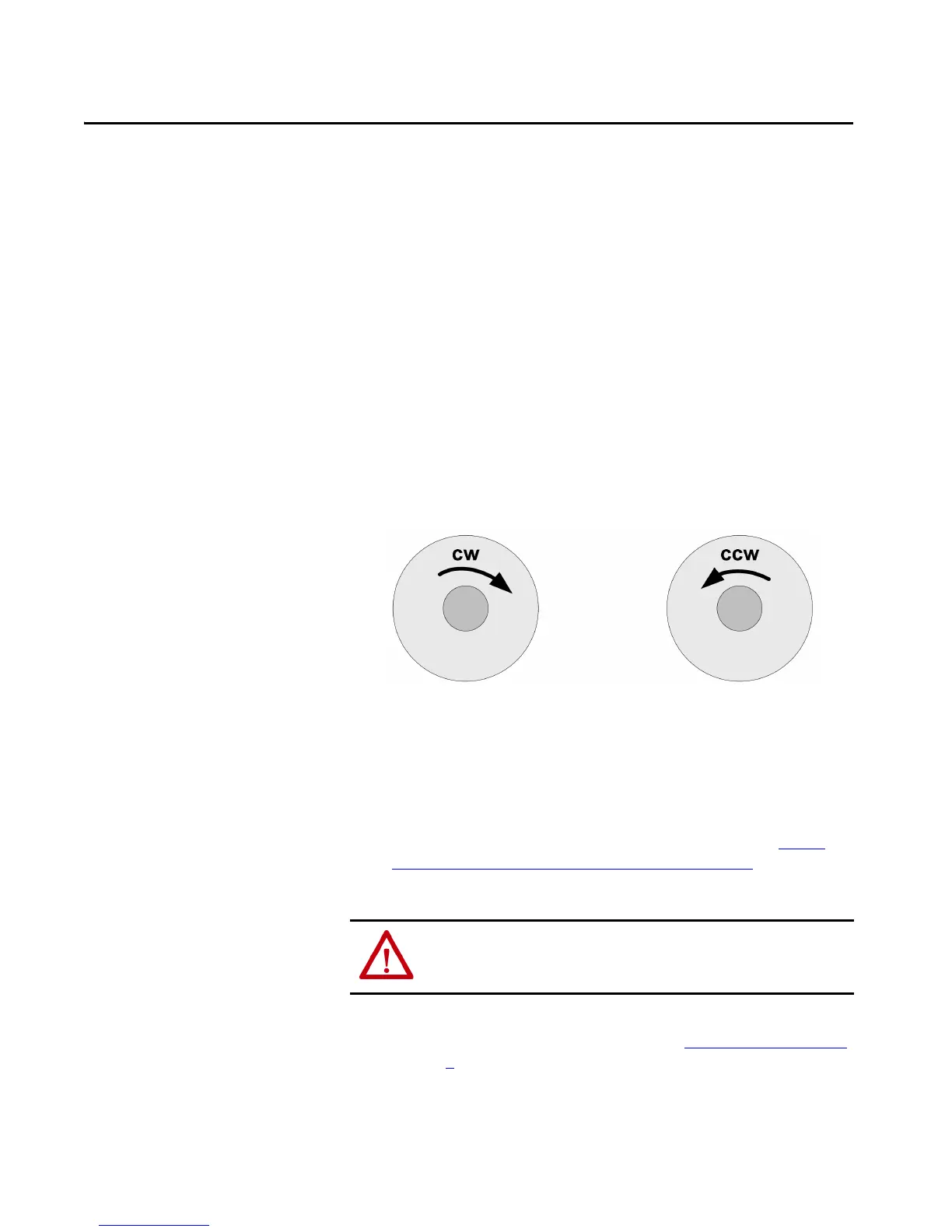
Shaft Rotation Direction
When you view the encoder from the shaft side, the shaft rotation is clockwise
(CW) or counterclockwise (CCW), as shown.
Figure 1
Mounting with a Solid Shaft
1. Be sure to select the proper size flexible coupling clamp to mate to the
encoder shaft, for example, 845–FC–*–*. See our website at http://
ab.rockwellautomation.com/Motion-Control/Encoders for encoder
accessories.
2. To determine the encoder mounting hole locations, use the dimension
drawings in the installation instructions (see “Related Documentation”
on page 7
).
3. Slide the flexible coupling onto the shaft, but do not tighten the set
screws.
ATTENTION: Do not rigidly connect the encoder shaft to the machine. A rigid
connection causes premature failure of the encoder or machine bearings.
Always use a flexible coupling.
 Loading...