Kinetix 5700 DC-bus Power Supplies 5
Rockwell Automation Publication 2198-IN009B-EN-P - June 2015
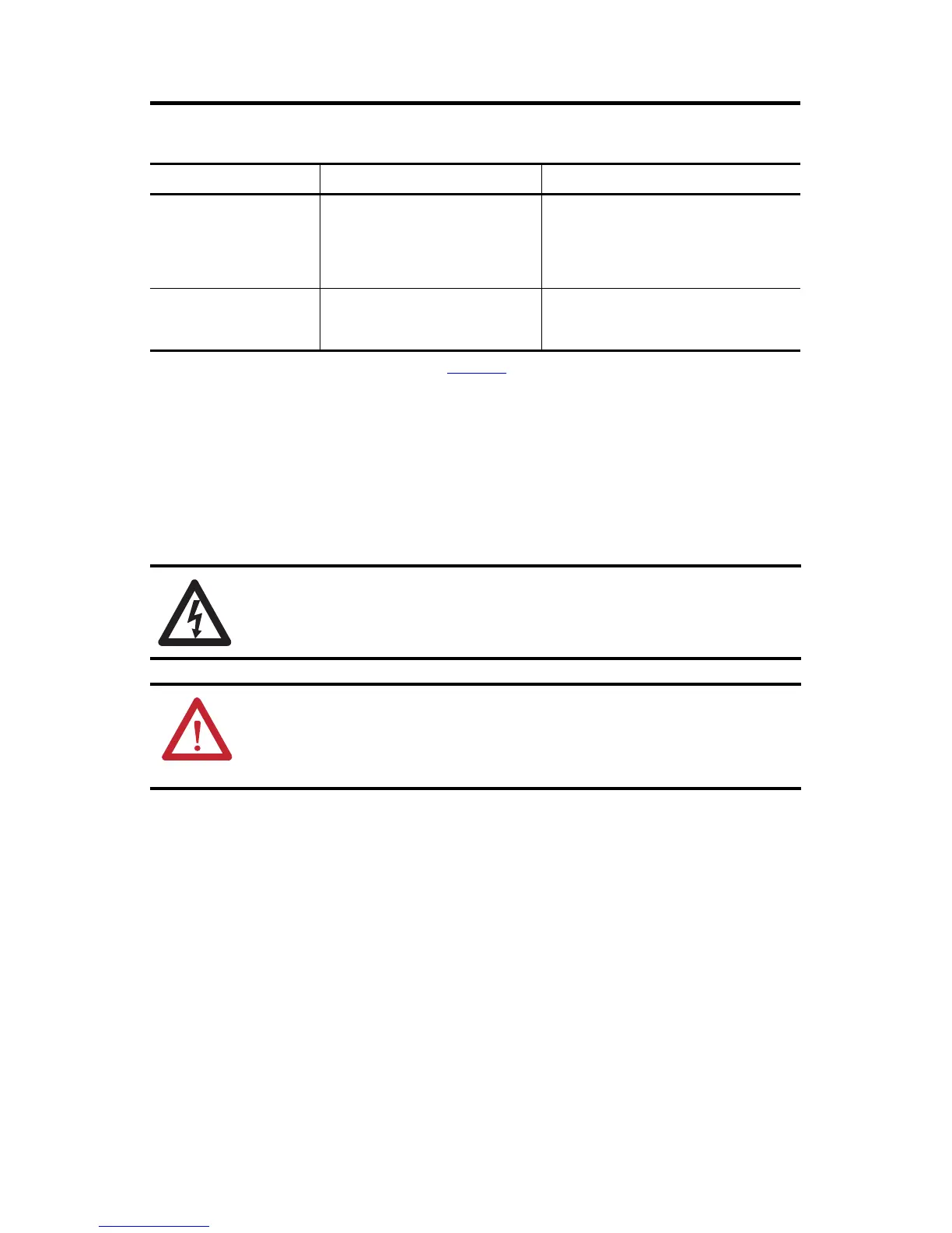
Grounding Screw Configurations
Install the DC-bus Power Supply
These procedures assume that you have prepared your panel and understand how to bond your
system. For installation instructions regarding equipment and accessories not included here, refer
to the instructions that came with those products.
Mount the DC-bus Power Supply
Observe these clearance requirements when mounting the DC-bus power supply:
• Additional clearance is required for cables and wires or the shared-bus connection
system connected to the top of the drive module.
• Additional clearance is required if other devices are installed above and/or below the
drive and have clearance requirements of their own.
• Additional clearance left and right of the drive module is required when mounted
adjacent to noise sensitive equipment or clean wire ways.
• The recommended minimum cabinet depth is 300 mm (11.81 in.).
Ground Configuration
(1)
(1) Refer to the Kinetix 5700 Servo Drives User Manual, publication 2198-UM002, for example configurations.
Grounding Screw Configuration Benefits of Configuration
Grounded (wye)
Installed
(default setting)
• UL and EMC compliance
• Reduced electrical noise
• Most stable operation
• Reduced voltage stress on components and
motor bearings
• AC-fed ungrounded
• Corner grounded
• Impedance grounded
Removed
• Helps avoid severe equipment damage when
ground fault occurs
• Reduced leakage current
SHOCK HAZARD: To avoid hazard of electrical shock, perform all mounting and wiring of the
Kinetix 5700 drive prior to applying power. Once power is applied, connector terminals can have
voltage present even when not in use.
ATTENTION: Plan the installation of your system so that you can perform all cutting, drilling,
tapping, and welding with the system removed from the enclosure. Because the system is of the
open type construction, be careful to keep any metal debris from falling into it. Metal debris or
other foreign matter can become lodged in the circuitry and result in damage to components.

 Loading...


