English-13
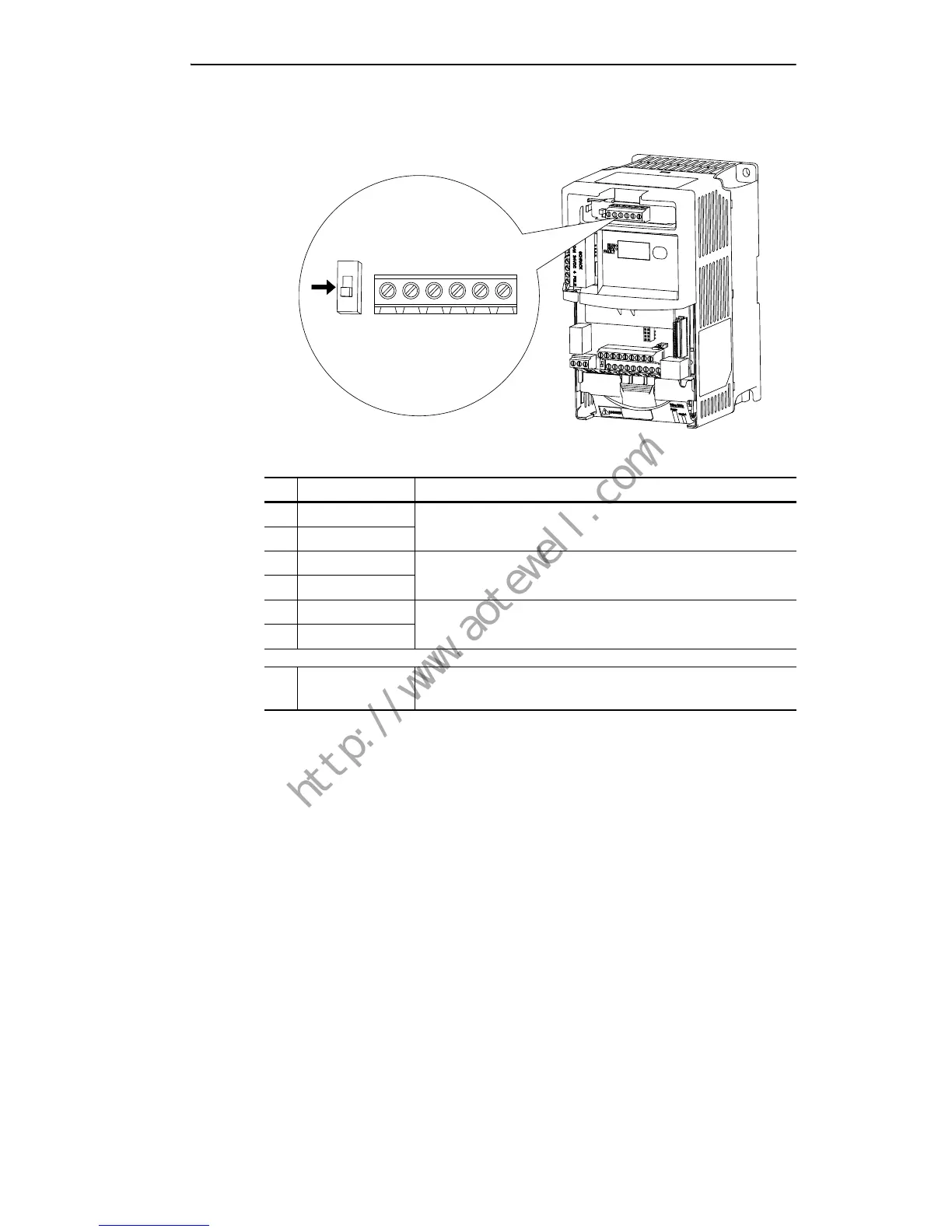
Encoder Interface
The PowerFlex 40P Encoder Interface can source 5 or12 volt power and
accept 5, 12 or 24 volt single ended or differential inputs.
Terminal Description
Important: A quadrature encoder provides rotor speed and direction.
Therefore, the encoder must be wired such that the forward
direction matches the motor forward direction. If the drive
is reading encoder speed but the position regulator or other
encoder function is not working properly, remove power to
the drive and swap the A and A (NOT) encoder channels or
swap any two motor leads. Drives using FRN 2.xx and
greater will fault when an encoder is incorrectly wired and
E216 [Motor Fdbk Type] is set to option 5 “Quad Check”.
No. Signal Description
+V 5V-12V Power
(1)
(1)
When using 12V Encoder power, 24V I/O power, maximum output current at I/O
Terminal 11 is 50 mA.
Internal power source 250 mA (isolated).
Cm Power Return
B- Encoder B (NOT)
Quadrature B input.
B Encoder B
A- Encoder A (NOT)
Single channel, pulse train, or quadrature A input.
A Encoder A
➊ Output DIP switch selects 12 or 5 volt power supplied at terminals “+V”
and “Cm” for the encoder.

 Loading...