English-2
• Mount the drive upright on a flat, vertical and level surface.
• Protect the cooling fan by avoiding dust or metallic particles.
• Do not expose to a corrosive atmosphere.
• Protect from moisture and direct sunlight.
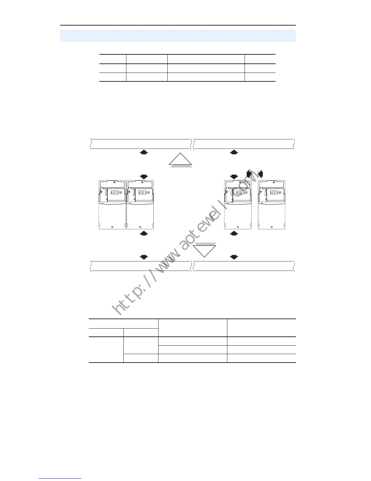
Minimum Mounting Clearances
See page 21 for mounting dimensions.
Ambient Operating Temperatures
Mounting Considerations
Frame Screw Size Screw Torque DIN Rail
B M4 (#8-32) 1.56-1.96 N-m (14-17 lb.-in.) 35 mm
C M5 (#10-24) 2.45-2.94 N-m (22-26 lb.-in.) –
Ambient Temperature Enclosure Rating Minimum Mounting
Clearances
Minimum Maximum
-10°C (14°F)
40°C (104°F)
IP 20/Open Type Use Mounting Option A
IP 30/NEMA 1/UL Type 1
(1)
(1)
Rating requires installation of the PowerFlex 40P IP 30/NEMA 1/UL Type 1 option kit.
Use Mounting Option B
50°C (122°F) IP 20/Open Type Use Mounting Option B

 Loading...