Rockwell Automation Publication 520-QS001A-EN-E - March 2014 3
PowerFlex 520-Series Adjustable Frequency AC Drive
Mounting Considerations
• Mount the drive upright on a flat, vertical and level surface.
• Protect the cooling fan by avoiding dust or metallic particles.
• Do not expose to a corrosive atmosphere.
• Protect from moisture and direct sunlight.
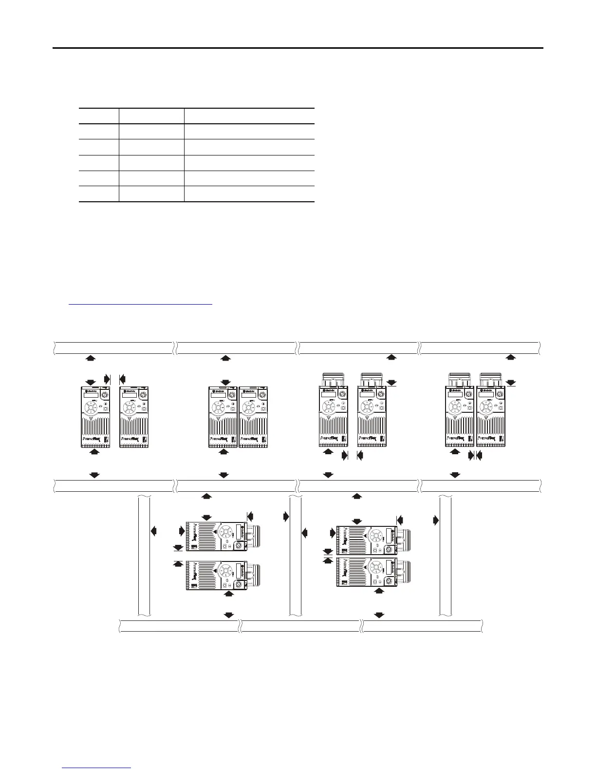
Minimum Mounting Clearances
See Dimensions and Weight on page 32 for mounting dimensions.
(1) For Frame E with Control Module Fan Kit only, clearance of 95 mm (3.7 in.) is required.
(2) For Frame E with Control Module Fan Kit only, clearance of 12 mm (0.5 in.) is required.
Frame Screw Size Screw Torque
A M5 (#10...24) 1.56...1.96 Nm (14...17 lb-in.)
B M5 (#10...24) 1.56...1.96 Nm (14...17 lb-in.)
C M5 (#10...24) 1.56...1.96 Nm (14...17 lb-in.)
D M5 (#10...24) 2.45...2.94 Nm (22...26 lb-in.)
E M8 (5/16 in.) 6.0...7.4 Nm (53...65 lb-in.)
25 mm
(1.0 in.)
25 mm
(1.0 in.)
(2)
(2)
25 mm
(1.0 in.)
50 mm
(2.0 in.)
50 mm
(2.0 in.)
(1)
50 mm
(2.0 in.)
(1)
50 mm
(2.0 in.)
(1)
50 mm
(2.0 in.)
50 mm
(2.0 in.)
50 mm
(2.0 in.)
Esc
Sel
Esc
Sel
Esc
Sel
Esc
Sel
50 mm
(2.0 in.)
50 mm
(2.0 in.)
50 mm
(2.0 in.)
50 mm
(2.0 in.)
E
s
c
S
e
l
E
s
c
S
e
l
50 mm
(2.0 in.)
50 mm
(2.0 in.)
50 mm
(2.0 in.)
50 mm
(2.0 in.)
50 mm
(2.0 in.)
(1)
Esc
S
el
Esc
Se
l
Esc
Sel
Esc
Sel
Esc
Sel
Esc
Sel
Vertical, Zero Stacking
No clearance between drives.
Horizontal, Zero Stacking with Control Module Fan Kit
No clearance between drives.
Vertical Vertical, Zero Stacking with
Control Module Fan Kit
No clearance between drives.
Vertical with Control Module Fan Kit
Horizontal with Control Module Fan Kit

 Loading...


