Rockwell Automation Publication 520-UM001G-EN-E - September 2014 189
Appendix C
RS485 (DSI) Protocol
PowerFlex 520-series drives support the RS485 (DSI) protocol to allow efficient
operation with Rockwell Automation peripherals. In addition, some Modbus
functions are supported to allow simple networking. PowerFlex 520-series drives
can be multi-dropped on an RS485 network using Modbus protocol in RTU
mode.
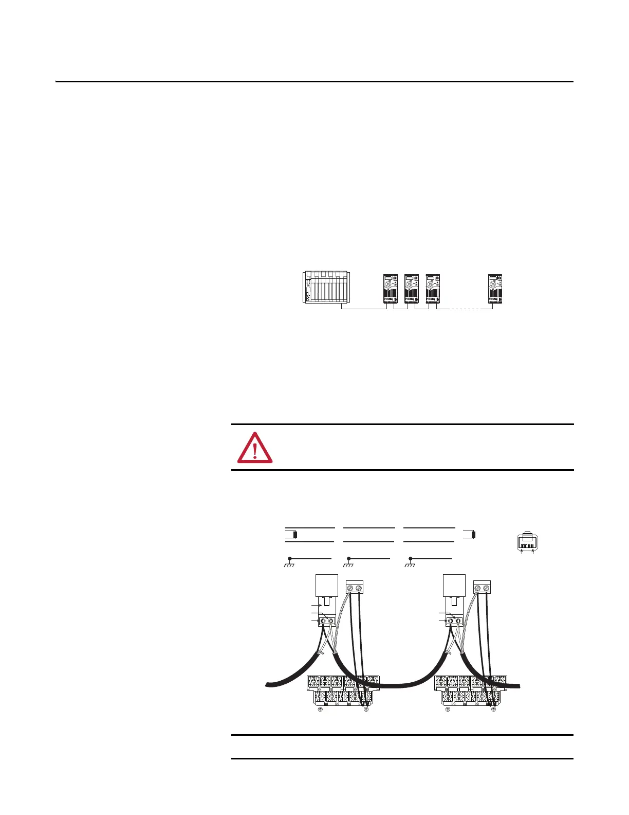
PowerFlex 520-Series Drive Network
For information regarding EtherNet/IP or other communication protocols, refer
to the appropriate user manual.
Network Wiring
Network wiring consists of a shielded 2-conductor cable that is daisy-chained
from node to node.
Network Wiring Diagram Example
Controller
Esc
Sel
Esc
Sel
Esc
Sel
Esc
Sel
ATTENTION: Never attempt to connect a Power over Ethernet (PoE) cable to the
RS485 port. Doing so may damage the circuitry.
The shield is connected at ONLY ONE end of each cable segment.
C1 C2
Master
4
5
TxRxD-
TxRxD+
TxRxD-
TxRxD+
TxRxD-
TxRxD+
Shield Shield Shield
120 ohm resistor
120 ohm resistor
X X X
FRONT
PIN 8PIN 1
TxRxD-
TxRxD+
RS485
(DSI)
AK-U0-RJ45-TB2P
V/T2T/L3S/L2R/L1 U/T1 W/T3
BR+
BR-
DC-
DC+
C1 C2
TxRxD-
TxRxD+
RS485
(DSI)
V/T2T/L3S/L2R/L1 U/T1 W/T3
BR+
BR-
DC-
DC+
PowerFlex 525
Node 1
4
5
PowerFlex 523
Node 2
4
5
PowerFlex 525
Node “n”

 Loading...


