Rockwell Automation Publication 520-UM001G-EN-E - September 2014 31
Installation/Wiring Chapter 1
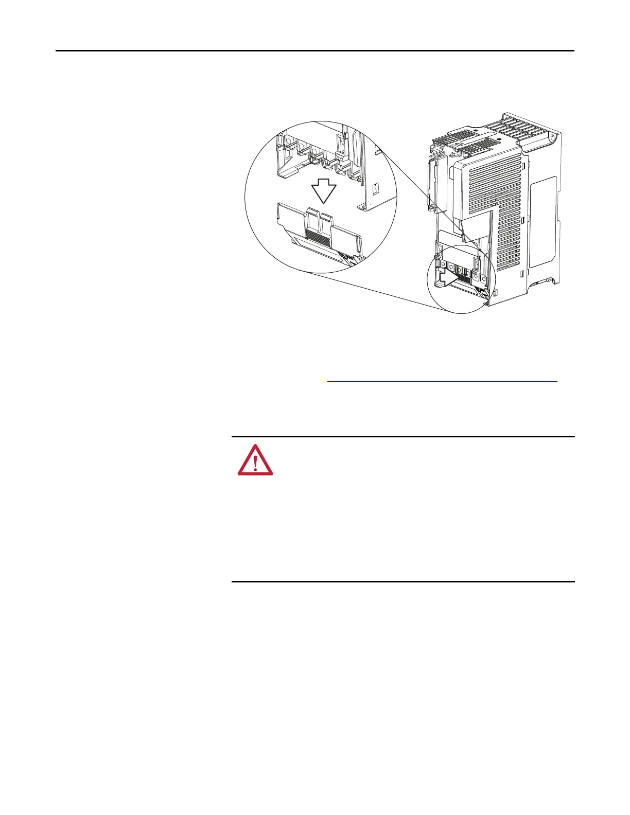
2. Press and hold down the locking tab on the terminal guard.
3. Slide the terminal guard down to remove from the Power Module.
Re-attach the terminal guard when wiring is complete.
To access the power terminals for Frame A, you need to separate the Power and
Control Modules. See Separating the Power and Control Module
on page 27 for
instructions.
Power Wiring
Motor Cable Types Acceptable for 100...600 Volt Installations
A variety of cable types are acceptable for drive installations. For many
installations, unshielded cable is adequate, provided it can be separated from
sensitive circuits. As an approximate guide, allow a spacing of 0.3 m (1 ft) for
every 10 m (32.8 ft) of length. In all cases, long parallel runs must be avoided. Do
not use cable with an insulation thickness less than 15 mils (0.4 mm/0.015 in.).
Do not route more than three sets of motor leads in a single conduit to minimize
“cross talk”. If more than three drive/motor connections per conduit are required,
shielded cable must be used.
ATTENTION: National Codes and standards (NEC, VDE, BSI, etc.) and local codes
outline provisions for safely installing electrical equipment. Installation must
comply with specifications regarding wire types, conductor sizes, branch circuit
protection and disconnect devices. Failure to do so may result in personal injury
and/or equipment damage.
ATTENTION: To avoid a possible shock hazard caused by induced voltages,
unused wires in the conduit must be grounded at both ends. For the same
reason, if a drive sharing a conduit is being serviced or installed, all drives using
this conduit should be disabled. This will help minimize the possible shock
hazard from “cross coupled” power leads.

 Loading...


