54 Rockwell Automation Publication 520-UM001G-EN-E - September 2014
Chapter 1 Installation/Wiring
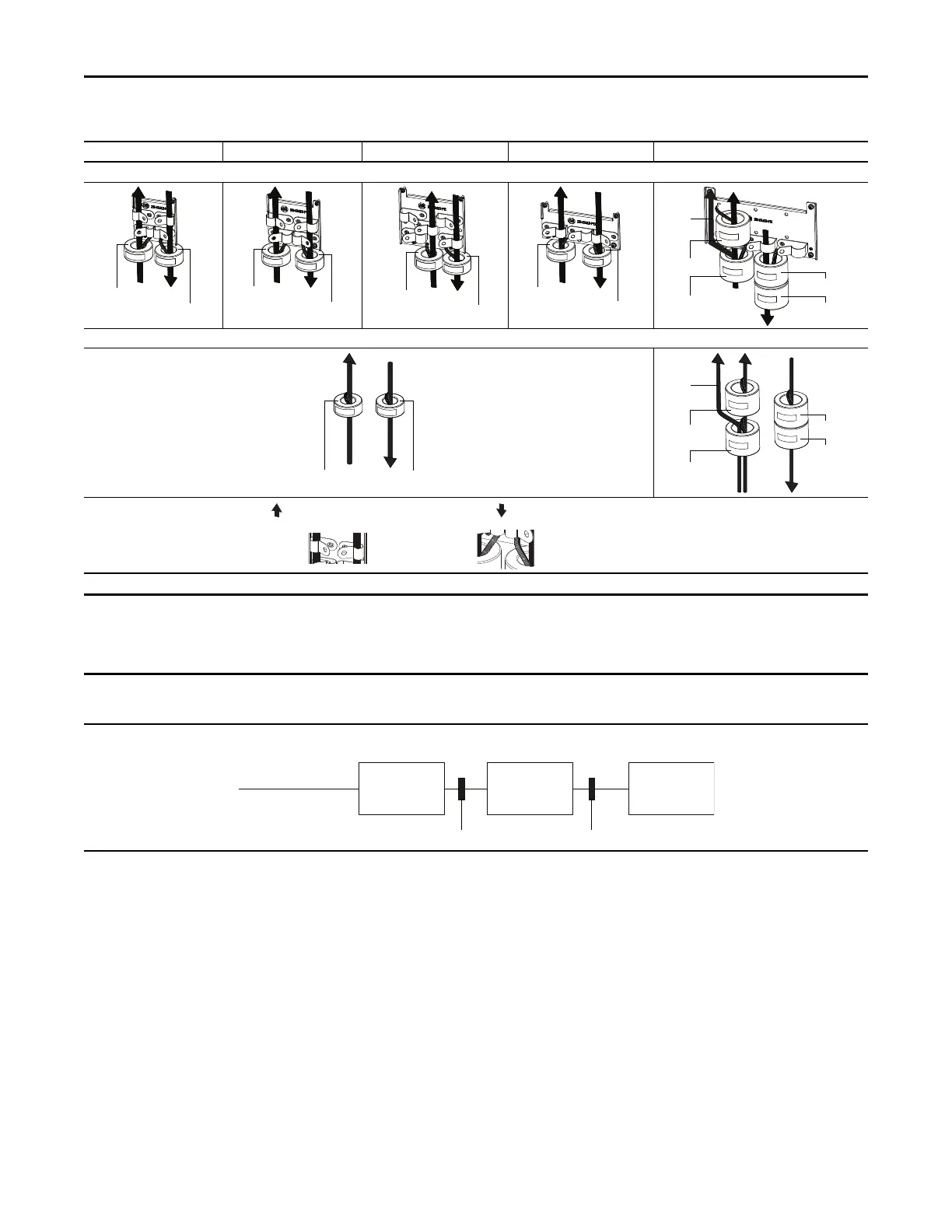
Recommended Placement of EMC Cores
Frame A Frame B Frame C Frame D Frame E
With optional EMC plate (25-EMC-Fx)
Without EMC plate
CORE-E-1
CORE-E-2
CORE-E-3
CORE-E-4
Ground
cable
CORE-E-1
CORE-E-2
CORE-E-3
CORE-E-4
Ground
cable
Shows contact to
shielded layer
Secure EMC core by
using cable/zip ties
Output cable from drive (Shielded)
Input cable to drive (Shielded or Unshielded)
The ground cable/shield for both input and output must pass through the EMC core(s), except for the following:
• Frame E drives with internal filters where the grounded input cable must not pass through EMC CORE-E-1.
• 600V drives with external filters where the grounded output cable must not pass through the EMC core(s).
Recommended Placement of EMC Cores Relative to External Filter
Input core Output core
Incoming power
EMC Filter Drive Motor
All Frame sizes

 Loading...


