PowerFlex 700 Technical Data
20B-TD001F-EN-P 7
Factory Installed Options
Conformal Coat (Position d = M) ‡
Description Frame
Conformal Coat
Printed circuit boards are coated with HumiSeal 1B73
acrylic coating to provide improved resistance to dust and
moisture. Consult factory for additional details.
0…10
‡ Only available with Vector Control option.
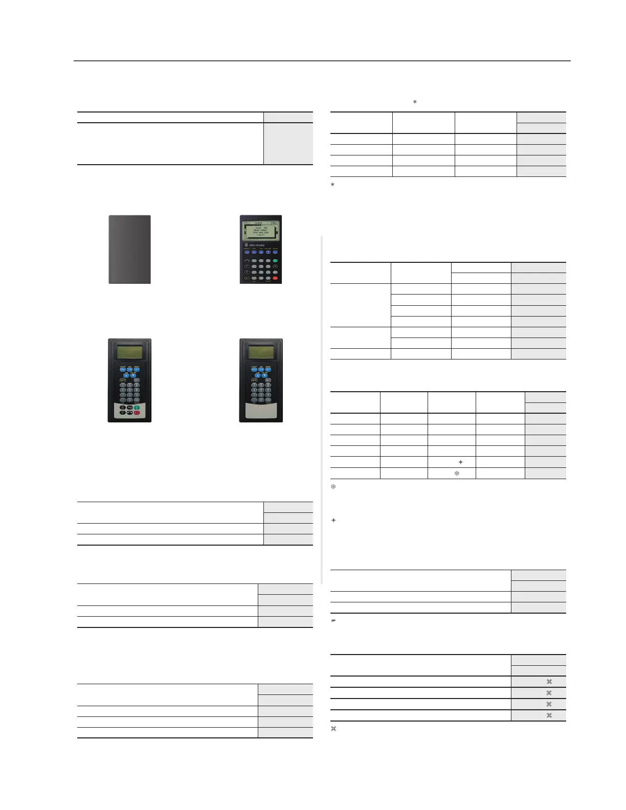
Human Interface and Wireless Interface Modules (Pos. e)
Cat. Code: 0
No HIM (Blank Plate)
IP20, NEMA/UL Type 1
Cat. Code: 3
LCD Display, Full Numeric
Keypad
IP20, NEMA/UL Type 1
Cat. Code: J
Remote (Panel Mount) LCD
Display, Full Numeric Keypad
IP66, NEMA/UL Type 4x/12
Cat. Code: K
Remote (Panel Mount) LCD
Display, Programmer Only
IP66, NEMA/UL Type 4x/12
Documentation
Description
Cat. Code
(Position f)
Manual
A
No Manual
N
Internal Brake IGBT
Drive Input Voltage Brake IGBT Frame
Cat. Code
(Position g)
208…480V AC Standard 0…3
Y
208…480V AC Optional 4
Y
208…690V AC Optional 5
Y
208…690V AC Optional 6
Y
The Internal Brake IGBT option cannot be field installed.
Internal Dynamic Brake Resistors
These resistors have a limited duty cycle. Refer to the PowerFlex
Dynamic Braking Selection Guide to determine if an internal
resistor will be sufficient. An external resistor may be required.
Drive Input
Voltage Frame
Brake Resistance
Cat. Code
Ω
(Position h)
208…240V AC
062
Y
1 (2…5 Hp) 62
Y
1 (7.5 Hp) 22
Y
222
Y
380…600V AC
0115
Y
1115
Y
380…480V AC 2 68
Y
Internal EMC Filter and Common Mode Choke
Drive Input
Voltage Frame CE Filter
Common
Mode Choke
Cat. Code
(Position i)
208…240V AC 3
§ w/Filter with Choke A
208…240V AC 0…3 w/Filter No Choke
B
208…240V AC 4…6 w/Filter with Choke
A
380…480V AC 0…6 w/Filter with Choke
A
380…480V AC 7…10
No Filter
No Choke N
600…690V AC 0…6
w/Filter
with Choke A
Note: 600V class drives below 77 Amps (Frames 0-4) are declared to meet
the Low Voltage Directive. It is the responsibility of the user to determine
compliance to the EMC directive.
§ Applies only to the 52 Amp drive.
Frames 7…10, 400/480V AC drives meet CE certification requirements
when installed per recommendations (refer to the User Manual, publication
20B-UM002).
Internal Communication Adapters
Description
Cat. Code
(Position j)
ControlNet™ Communication Adapter (Coax)
C
DeviceNet™ Communication Adapter
D
EtherNet/IP™ Communication Adapter
E
Control and I/O Options
Control
Cat. Code
(Position k)
Vector Control (Series B) - 24V DC
‡♠
C
Vector Control (Series B) - 115V AC
‡♠
D
‡ Vector Control option utilizes DPI Only.
♠ Frames 7…10 MUST select a Vector Control option.
Feedback Options (Vector Control Only)
Description
Cat. Code
(Position l)
No Encoder
0
12V/5V Encoder
ä 1
Encoder option can also be used as a pulse input.
Special Firmware
Description
Cat. Code
(Position m…n)
60 Hz Maximum
NNAD
Cascading Fan/Pump Control
NNAE
82 Hz Maximum
NNAX
Pump Off (for Pump Jack)
NNBA
Must be used with Vector Control option C or D (position k), Frames 0…6
onl
.

 Loading...


