PowerFlex 700 Technical Data
72 20B-TD001F-EN-P
Specifications
Control and Performance
Category
Frames
Specification
0…4
5…6 7…10
230…480V 600V
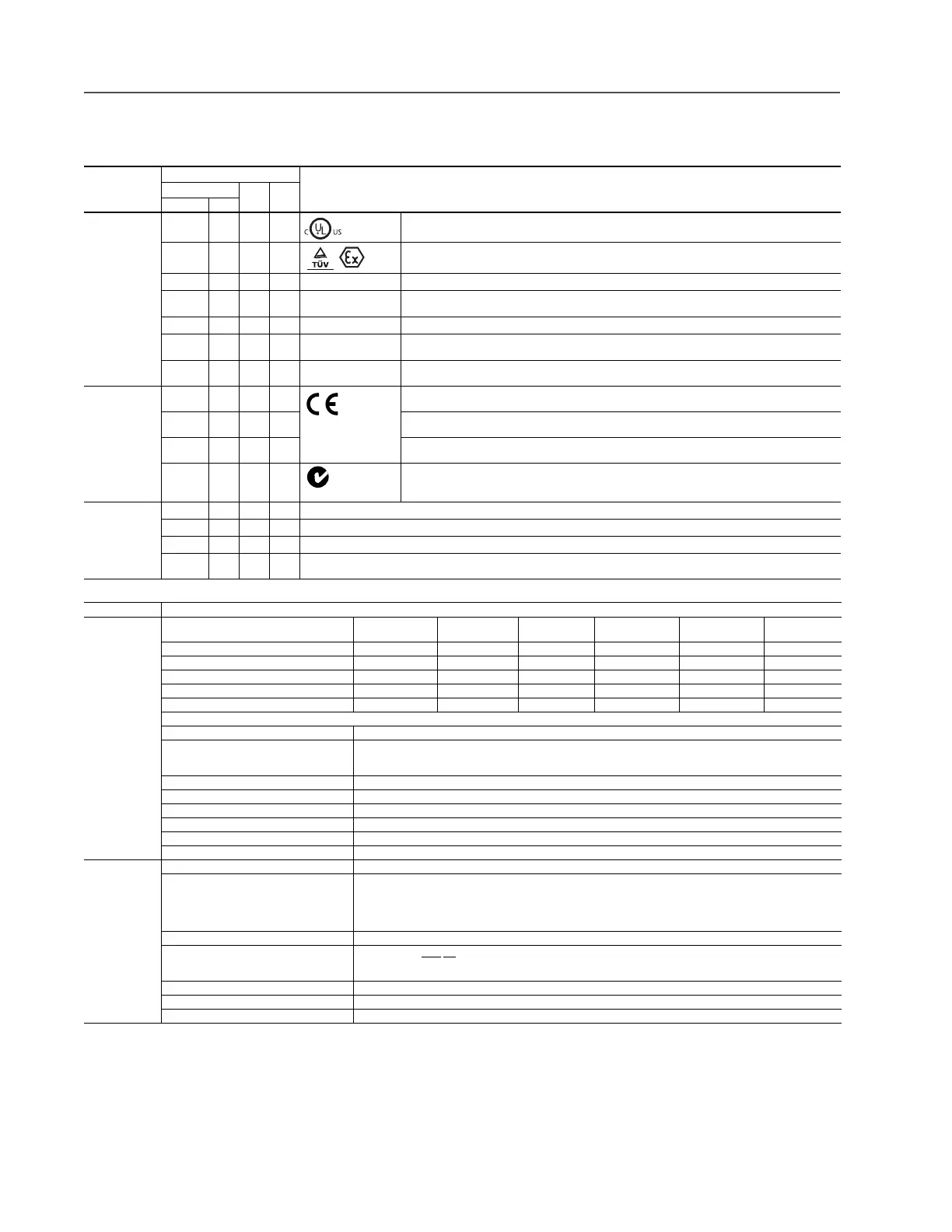
Agency Listings,
Certification or
Tests
✔✔✔✔
Listed to UL508C and CAN/CSA-C22.2 No. 14-05.
Packaged drives may be listed to UL508A
✔✔✔✔
EC-Type-Examination Certificate TUV 05 ATEX 7153 for directive 94/9/EC: Safe turn off of certified ATEX motors used
in Group II Category (2) GD potentially explosive atmospheres.
✔✔
EPRI /SEMIF47 EPRI Quality Star Certificates SEMIF47.115 and SEMIF47.127 for SEMI F47 compliance, 480V units tested
✔✔
ABS
American Bureau of Shipping MA Certificate 08-HS303172B/1-PDA for auxiliary services on AB Classed
vessels and offshore platforms
✔✔
LLoyd’s Register Lloyd’s Register Type Approval Certificate 08 / 60015 (marine certification)
✔✔✔
RINA RINA Type Approval Certificate ELE283205CS (Registo Italiano Navale - marine certification)
✔✔✔
Trentec Tested by Trentec to be compliant with AC156 Acceptance Criteria for Seismic Qualification Testing of Nonstructural
Components and 2003 International Building Code for worst-case seismic level for USA excluding site class F
Rockwell
Automation
Certifications
Certified by Rockwell Automation to be in conformity with the essential requirements of the applicable European
Directives and the standards referenced below have been applied:
✔✔✔✔
2006/95/EC (Low Voltage Directive)
EN 50178 Electronic Equipment for use in Power Installations
✔✔✔
2004/108/EC (EMC Directive)
EN 61800-3 Adjustable Speed electrical power drive systems - Part 3: EMC requirements and specific test methods.
✔✔✔
Certified by Rockwell Automation to be in conformity with the requirements of the applicable Australian legislation and
the standards referenced below:
IEC 61800-3
Designed to Meet
Applicable
Requirements
✔✔✔✔
CMAA Specification #70 (Crane Manufacturers of America Association)
✔✔✔✔
NFPA 70 - US National Electrical Code
✔✔✔✔
NEMA ICS 7.1 - Safety Standards for Construction and Guide for Selection, Installation, and Operation of Adjustable Speed Drive Systems
✔✔✔✔
IEC 61800-2 Adjustable Speed Electrical Power Drive Systems - Part 2: General Requirements - Rating specifications for low voltage adjustable
frequency AC power drive systems.
Category Specification
Protection Drive 200-
208V
240V 380/400V 480V 600V
Frames 0…4
600/690V
Frames 5…6
AC Input Overvoltage Trip: 285VAC 285VAC 570VAC 570VAC 716VAC 818VAC
AC Input Undervoltage Trip: 120VAC 138VAC 233VAC 280VAC 345VAC 345VAC
Bus Overvoltage Trip: 405VDC 405VDC 810VDC 810VDC 1013VDC 1162VDC
Bus Undervoltage Shutoff/Fault: 153VDC 153VDC 305VDC 305VDC 381VDC 437V DC
Nominal Bus Voltage: 281VDC 324VDC 540VDC 648VDC 810VDC 932VDC
All Drives
Heat Sink Thermistor: Monitored by microprocessor overtemp trip
Drive Overcurrent Trip
Software Overcurrent Trip:
Hardware Overcurrent Trip:
200% of rated current (typical)
220…300% of rated current (dependent on drive rating)
Line transients: up to 6000 volts peak per IEEE C62.41-1991
Control Logic Noise Immunity: Showering arc transients up to 1500V peak
Power Ride-Thru: 15 milliseconds at full load
Logic Control Ride-Thru: 0.5 seconds minimum, 2 seconds typical
Ground Fault Trip: Phase-to-ground on drive output
Short Circuit Trip: Phase-to-phase on drive output
Environment Altitude: 1000 m (3300 ft) max. without derating
Maximum Surrounding Air Temperature without
Derating - IP20, NEMA/UL Type Open:
Frames 0…6
Frames 7…10
0 to 50 degrees C (32 to 122 degrees F), typical. See pages 33 through 36 for exceptions.
0 to 40 degrees C (32 to 104 degrees F) for chassis (heatsink)
0 to 65 degrees C (32 to 149 degrees F) for control (front of backplane)
Storage Temperature (all const.): –40 to 70 degrees C (–40 to 158 degrees F)
Atmosphere: Important: Drive must
not be installed in an area where the ambient atmosphere contains volatile or corrosive gas, vapors or dust.
If the drive is not going to be installed for a period of time, it must be stored in an area where it will not be exposed to a corrosive
atmosphere.
Relative Humidity: 5 to 95% non-condensing
Shock: 15G peak for 11ms duration (±1.0 ms)
Vibration: 0.152 mm (0.006 in.) displacement, 1G peak
II (2) G D
N223

 Loading...


