Connector Descriptions C-11
Table C.Q Right Side Main Cooling Fan Inverter Connections
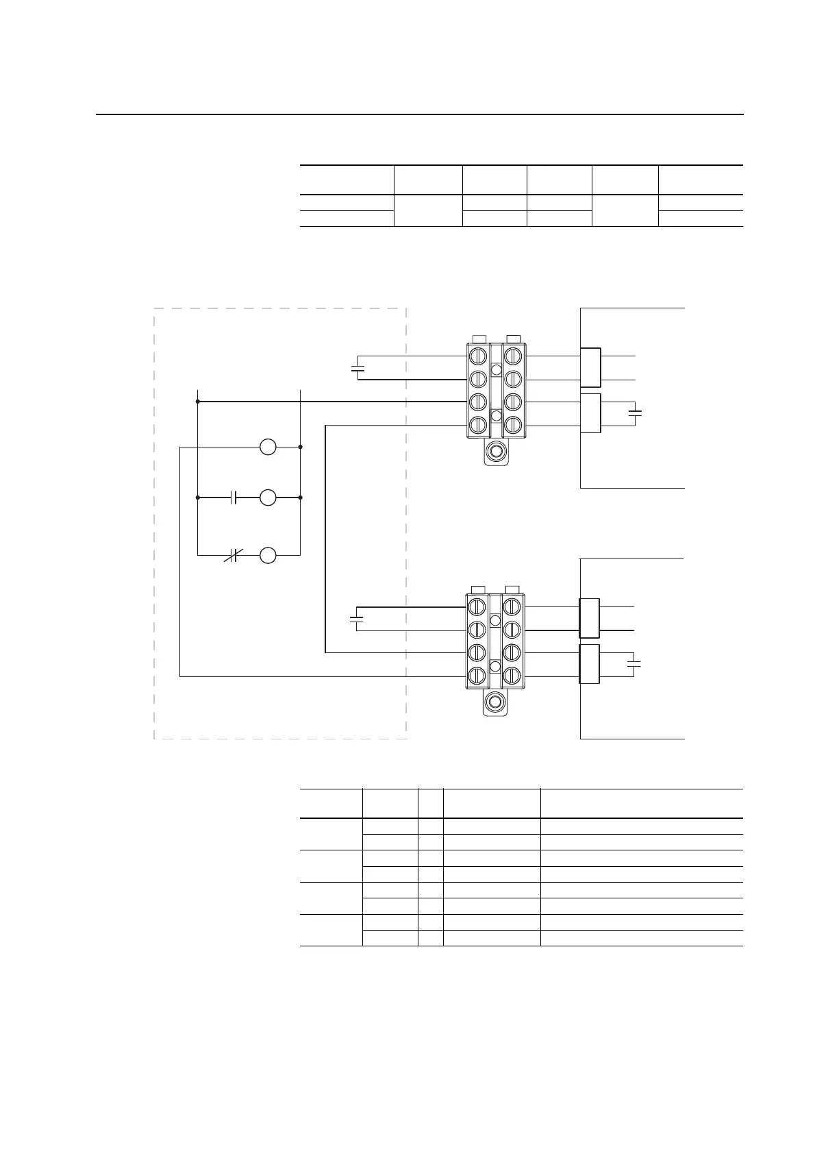
Figure C.8 X50 Terminal Block Connectors
Table C.R X50 Terminal Block Precharge Circuit Connections
Description
Fan Inverter
Connector Pin Number Pin Number
Fan Inverter
Connector Description
+15V dc power X3 2 4 X3 +15V dc power
Fan Alarm 4 2 Fan Alarm
Customer Connections Drive Connections
Terminal Blocks
CR1
Pilot Relay
CR1
M
Main DC Contactor
M
CR2
Precharge
M
Example External Precharge Circuitry
For DC Input Only
(Do Not Install on AC Input Drives)
+24V DC
0V DC
1
2
3
4
25
26
21
23
X15
X9
ASIC Board #1X50 #1
Charge
Relay
+24V DC
0V DC
1
2
3
4
25
26
21
23
X15
X9
ASIC Board #2X50 #2
Charge
Relay
M
ASIC Board
Connector Terminal to X50 Terminal Block Description
X9 on ASIC
Board #1
25 . . . 1 Precharge Complete Signal
26 . . . 2 Precharge Complete Signal
X15 on ASIC
Board #1
21 . . . 3 Charge Relay Contact
23 . . . 4 Charge Relay Contact
X9 on ASIC
Board #2
25 . . . 1 Precharge Complete Signal
26 . . . 2 Precharge Complete Signal
X15 on ASIC
Board #2
21 . . . 3 Charge Relay Contact
23 . . . 4 Charge Relay Contact

 Loading...


