Access Procedures 3-3
Understanding the Torque Figures in Assembly Diagrams
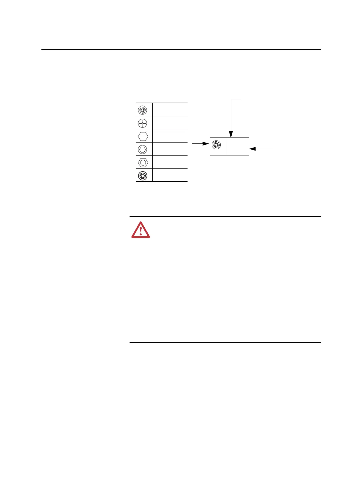
Icons and numbers in the assembly diagrams indicate how to tighten
hardware:
Removing Power from the
Drive
PZ2
4 N-m
(35 lb.-in.)
Tool Type and Size
PZ indicates POZIDRIV screwdriver bit
P indicates Phillips screwdriver bit
Tightening Torque
Fastener Type
POZIDRIV Screw
Phillips Screw
Hexagonal Bolt
or Standoff
Hexagonal
Screw
Hexagonal Nut
Torx Head Screw
!
ATTENTION: To avoid an electric shock hazard, verify that the
voltage on the bus capacitors has discharged before performing
any work on the drive. Measure the DC bus voltage at the DC+ &
DC- terminals. The voltage must be zero.
Remove power before making or breaking cable connections.
When you remove or insert a cable connector with power
applied, an electrical arc may occur. An electrical arc can cause
personal injury or property damage by:
x sending an erroneous signal to your system’s field devices,
causing unintended machine motion
x causing an explosion in a hazardous environment
Electrical arcing causes excessive wear to contacts on both the
module and its mating connector. Worn contacts may create
electrical resistance.

 Loading...


