2-2 Component Test Procedures
Viewing the 700S Diagnostic
LEDs
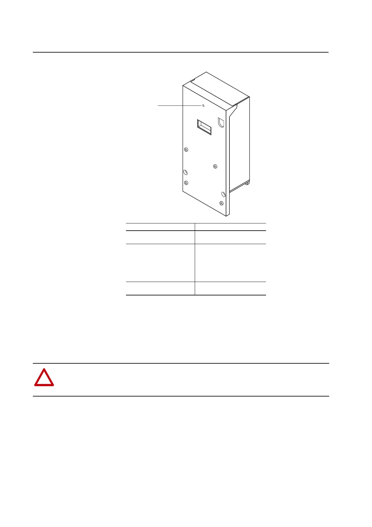
The PowerFlex 700S contains a Run LED, controller LEDs, and SynchLink
LEDs. These LEDs are only operational when the drive is energized and are
only visible when the drive door is open. The status of these LEDs can also
be viewed from the HIM or from an application program (e.g.,
DriveExplorer™) in parameter 554 [LED Status]. This feature is only
available with DriveLogix version 15.03 or later.
LED Indication
Steady The drive is operational and has
no faults
Flashing Quickly x Switching power supply
overload
x Rectifier Board fault
x Fan or fan inverter fault
x Brake Chopper fault
x Fiber Optic Adapter Board Fault
Flashing Slowly Bad connection between circuit
boards, check all connections
LED visible through
this hole
!
ATTENTION: The RUN LED and the controller LEDs are only operational when the drive is energized.
Servicing energized equipment can be hazardous. Severe injury or death can result from electrical shock, burn
or unintended actuation of controlled equipment. Follow Safety related practices of NFPA 70E, ELECTRICAL
SAFETY FOR EMPLOYEE WORKPLACES. DO NOT work alone on energized equipment!

 Loading...


