Access Procedures 3-27
Installation
Install the fans in reverse order of removal, while referring to Torque
Specifications on page 3-1.
Removing the ASIC Boards
Removal
1. Remove power from the drive (Removing Power from the Drive on
page 3-3).
2. Remove the covers from the power structures. Refer to Removing the
Covers from the Power Structures on page 3-15.
3. On Power Structure 1, remove the cover from the ASIC assembly and
the -DC bus connection from the cover.
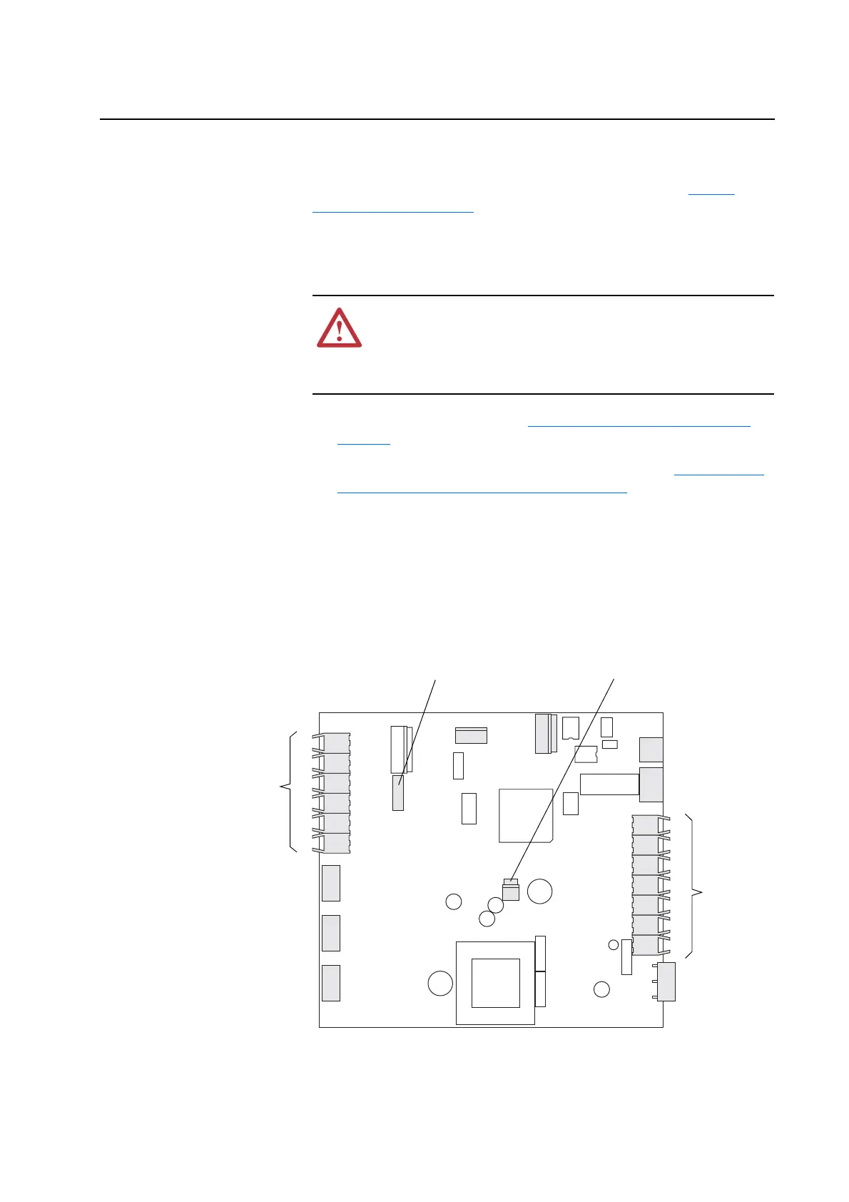
4. Unplug the fan that mounts on the cover from connector X1 of the
ASIC board.
5. Disconnect the Feedback board that mounts on the ASIC assembly
cover from connector X26 on the ASIC board.
!
ATTENTION: The sheet metal cover and mounting screws on
the ASIC Boards located on the power structures are energized at
(-) DC bus potential high voltage. Risk of electrical shock,
injury, or death exists if someone comes into contact with the
assembly.
H11
H12
H13
H8
H9
H10
X6
X9
X15
X3
X4
X5
X2
X1
H4
H5
H6
H1
H2
H3
H7
X26
X11
X26 Feedback Board connection
X1 Fan connection
Fiber-Optic
cable
connections
Fiber-Optic
cable
connections

 Loading...


