3-30 Access Procedures
Removing the Left-Side
Output Power Modules
Removal
Important: Do not attempt to disassemble the Output Power Modules.
Important: Always replace the Output Power Modules in pairs (do not
replace just one module).
1. Remove power from the drive (Removing Power from the Drive on
page 3-3).
2. Remove the covers from the power structures. Refer to Removing the
Covers from the Power Structures on page 3-15.
3. Remove the power structures from the drive cabinet (Removing the
Power Structures from the Drive Enclosure on page 3-25).
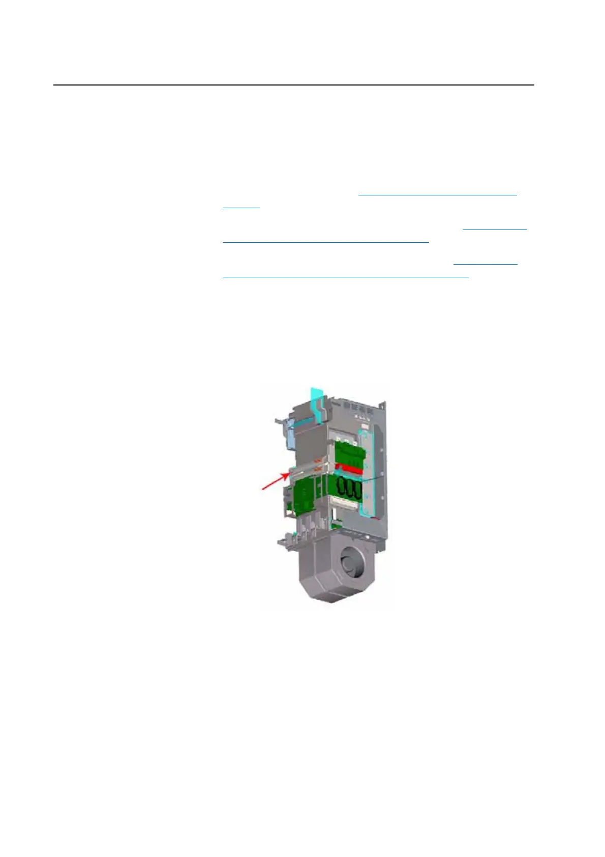
4. On Power Structure 1, remove the cable-tie which secures the Power
Module Circuit Board to the Adapter Board.
5. Disconnect the output leads from the bottom of the Output Power
Module.
6. Loosen, but do not remove, the screws that secure the Y Bus Bars to the
drive.
Y Bus Bars

 Loading...


