Component Test Procedures 2-3
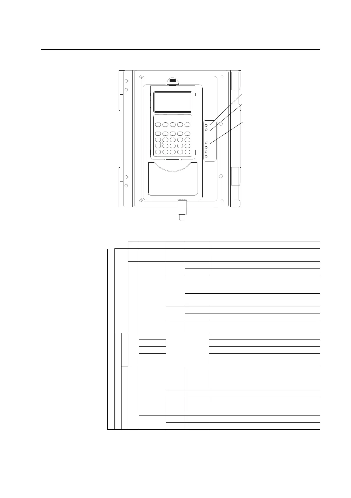
Table C Drive Status Indicator Descriptions
➋
➊
➌
# Name Color State Description
DRIVE
Power Structure
➊
PWR
(Power)
Green Steady Illuminates when power is applied to the drive.
➋
STS
(Status)
Green Flashing Drive ready, but not running & no faults are present.
Steady Drive running, no faults are present.
Yellow Flashing When running, a type 2 (non-configurable) alarm condition
exists, drive continues to run. When stopped, a start inhibit
exists and the drive cannot be started.
Steady A type 1 (user configurable) alarm condition exists, but
drive continues to run.
Red Flashing A fault has occurred.
Steady A non-resettable fault has occurred.
Red /
Ye l l o w
Flashing
Alternately
The drive is in flash recovery mode. The only operation
permitted is flash upgrade.
Control Assembly
Communications
➌
PORT Refer to the
Communication
Adapter User Manual
Status of DPI port internal communications (if present).
MOD Status of communications module (when installed).
NET A Status of network (if connected).
NET B Status of secondary network (if connected).
Control
(1)
SYNCHLINK Green Steady The module is configured as the time keeper.
or
The module is configured as a follower and
synchronization is complete.
Green Flashing The follower(s) are not synchronized with the time keeper.
Red Flashing The module is configured as a time master on SynchLink
and has received time information from another time
master on SynchLink.
ENABLE Green On The drive’s enable input is high.
Green Off The drive’s enable input is low.
(1)
SynchLink LEDS are located on the SynchLink daughtercard on the main circuit board in the control cassette.

 Loading...


